소개
This guide is to show you how to replace the SD card board. On the SD card board is not only the SD card reader itself, but there is also a micro switch that tells the camera if the battery door is closed. The camera will not turn on unless a signal is giving to the camera that the battery door is closed. Being that it is a small plastic switch, it is sometimes prone to breaking or having debris prevent it from working properly, stopping your camera from turning on.
The Phillips #000 screwdriver is marked as an optional tool as you can always use the JIS #000 screwdriver in its place (JIS screwdrivers won't damage Phillips head screws).
필요한 것
-
-
Pry open the rubber I/F terminal cap with your finger.
-
Remove the two M1.7x2.5mm JIS #000 screws that are underneath the I/F terminal cap.
-
Using a plastic pick, or another thin plastic prying tool, pop off the I/F terminal cover from the camera.
-
-
-
On the left side of the camera, remove the following screw:
-
One M1.7x6.0mm JIS #000 screw
-
On the right side, remove the following screws:
-
One M1.7x5.5mm JIS #000 screw
-
One M1.7x3.5mm JIS #000 screw
-
-
-
Slide the viewfinder eyepiece vertically upwards.
-
Start to pull the back cover partially off of the camera.
-
Disconnect the LCD screen ribbon cable from the main PCB board.
-
Use a plastic spudger to lift up the black locking tab.
-
Carefully pull out the ribbon cable from its connector using a pair of angled tweezers.
-
Finish pulling the back cover off of the camera body.
-
-
-
Remove the following screws from the front of the camera:
-
Two M1.7x5.5mm JIS #000 screws
-
On the bottom of the camera, remove the following screws:
-
Three M1.7x5.5mm JIS #000 screws
-
-
-
-
Remove the screws next to the viewfinder:
-
Two M1.7x2.5mm JIS #000 screws
-
One M2.0x8.9mm JIS #000 diopter screw
-
Remove the following screws from the top of the camera:
-
One M1.7x2.5mm JIS #000 screw
-
One M1.7x5.0mm Phillips #000 screw
-
-
-
Disconnect these two cables connected to the DC PCB board.
-
Use the same method as with removing the microphone cable, except with using a flathead 3.0mm screwdriver.
-
Gently wiggle the flathead screwdriver back and forth until the connectors comes free.
-
Gently lift the top cover up and off of the camera body, being careful that the loose cables do not snag on anything.
-
-
-
Locate these three ribbon cables located on the left side of the main PCB board.
-
Disconnect the ribbon cables.
-
Use a plastic spudger tool to carefully push up and disconnect the imaging sensor ribbon cable.
-
-
-
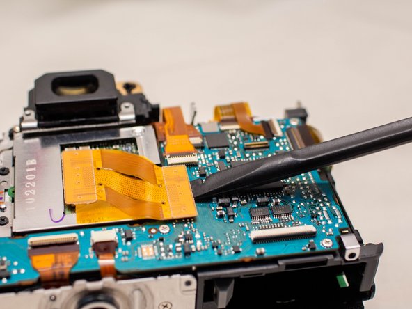
Locate the remaining seven ribbon cables connected to the main PCB board.
-
Gently push up on the plastic lock tabs to unlock each of the ribbon cable connectors. Be especially careful with the wide lock tab, as it is particularly fragile.
-
Disconnect each ribbon cable from the main PCB board.
-
-
-
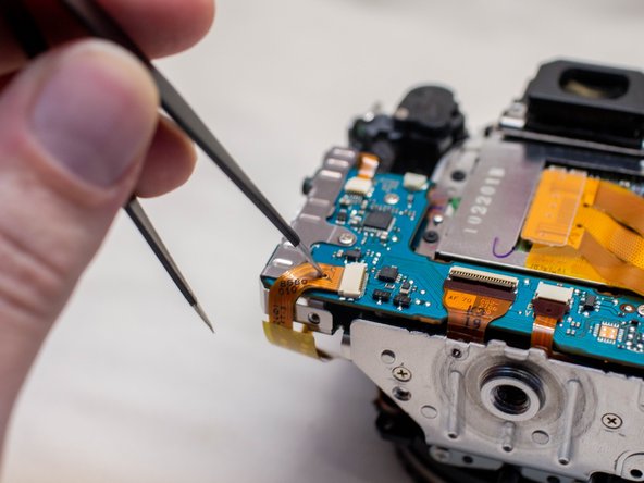
Disconnect the power cable from the SD card board using a 2.5mm screwdriver.
-
Carefully remove the ribbon cable from the SD card board using a pair of angled tweezers.
-


To reassemble your device, follow these instructions in reverse order.
To reassemble your device, follow these instructions in reverse order.
첨부 문서

팀
