소개
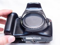
This guide shows you how to replace the image sensor in the camera. Please note that the image sensor is a very sensitive component and extreme care needs to be taken while replacing it to avoid damaging the new sensor or other components inside of the camera. It is highly recommended that you use an anti-static wrist strap while working inside the camera to prevent electrostatic discharge. Since this repair also involves the image sensor being exposed for a period of time, it's also recommended that you work in a clean environment with minimal dust to avoid dust from getting onto the sensor while it's exposed.
The image sensor on the Canon EOS Rebel T3, unlike with some models (such as the Rebel T3i) do not utilize springs to hold the image sensor at a specific height. Instead, a specifically sized washers is used to hold the image sensor at the correct height. This is good as it should allow for easier replacement of the image sensor without the need for recalibration as long as the same washer is put back in place during reassembly.
Removing the image sensor may also allow you to modify the sensor to make your camera into an infrared camera. This guide will not cover how to do an infrared conversion, but this guide does a decent job at showing the process of how to do it for the Canon EOS Rebel T3 (do so at your own risk).
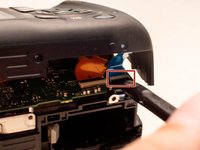
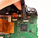
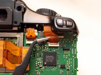
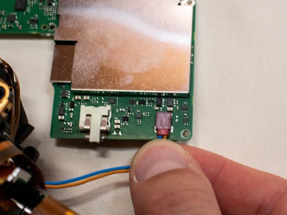
When you reinstall the main PCB board and are reconnecting the cables, note the single round black cable that leads to the top cover. This cable connects to the right side of the board and the connector is attached to the back of the board. To reconnect it, you simply need to push the cable down into the hole on the connector. This cable is a fiber optics cable used for the camera flash. Forgetting to reconnect this cable will likely cause the camera flash to no longer function.
The Phillips #000 screwdriver is marked as an optional tool as you can always use the JIS #000 screwdriver in its place (JIS screwdrivers won't damage Phillips head screws).
필요한 것
-
-
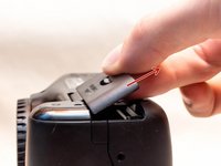
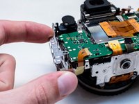
Pry open the rubber I/F terminal cap with your finger.
-
Remove the two M1.7x4.5mm JIS #000 screws that are underneath the I/F terminal cap.
-
Using a plastic pick, or another thin plastic prying tool, pop off the I/F terminal cover from the camera.
-
-
-
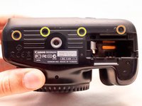
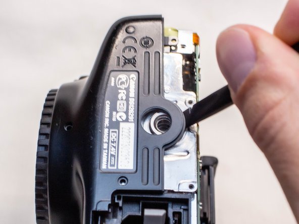
On the left side of the camera, remove the following screw:
-
One M1.7x4.5mm JIS #000 screw
-
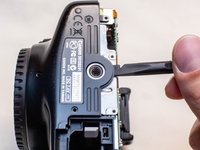
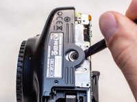
On the right side, remove the following screws:
-
One M1.7x5.5mm JIS #000 screw
-
One M1.7x4.5mm JIS #000 screw
-
-
-
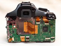
Carefully lift the back cover partially off of the camera.
-
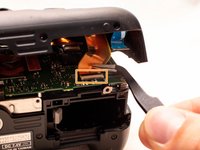
Disconnect the right most ribbon cables from the main PCB board.
-
Use a plastic spudger to lift up the black locking tab.
-
Pull out the ribbon cable from its connector using a pair of angled tweezers.
-
Remove the left ribbon cable using the same two steps as with the other ribbon cable.
-
-
-
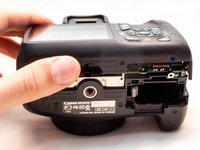
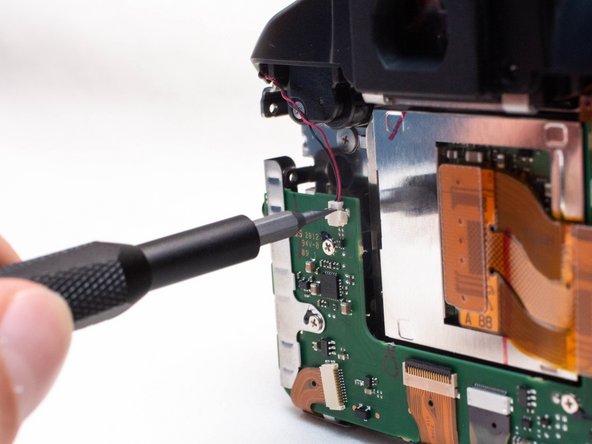
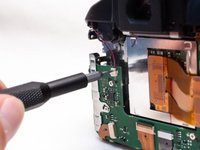
Remove the following screws on the front of the camera.
-
Two M1.7x5.5mm JIS #000 screws
-
-
-
-
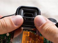
Push up and slide off the eyepiece.
-
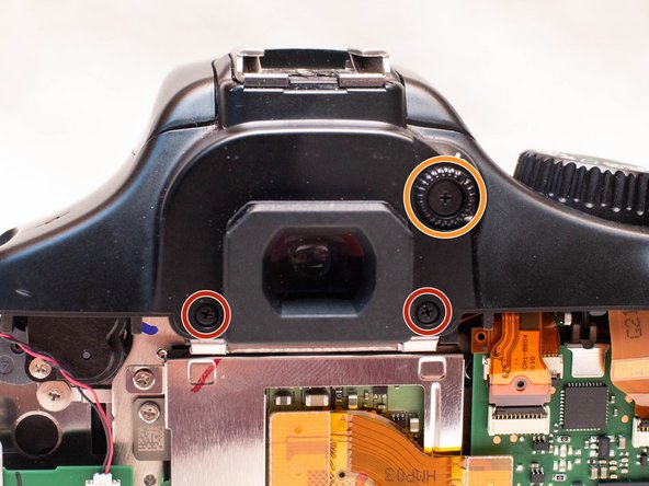
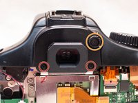
Remove the following screws:
-
Two M1.7x2.5mm JIS #000 screws
-
One M1.7x3.6mm JIS #000 diopter screw
-
-
-
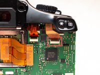
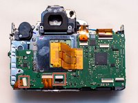
Locate the two ribbon cables on the main PCB board which are marked in the picture.
-
Disconnect the ribbon cables.
-
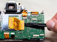
Use a plastic spudger tool to carefully push up and disconnect the imaging sensor ribbon cable.
-
-
-
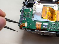
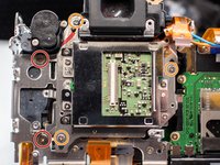
Locate the remaining four ribbon cables connected to the main PCB board.
-
Gently push up on the plastic lock tabs to unlock each of the ribbon cable connectors. Be especially careful with the wide lock tab, as it is particularly fragile.
-
Disconnect each ribbon cable from the main PCB board.
-
-
-
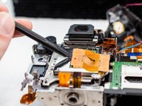
Using a plastic spudger tool, carefully push up and disconnect the ribbon cable from the image sensor.
-
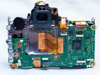
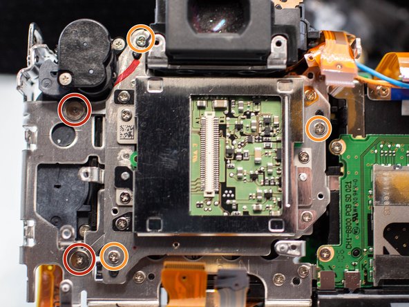
Remove the following screws from the image sensor:
-
Two M1.7x1.6mm JIS #000 screws
-
Three M1.7x5.5mm Phillips #000 screws
-


To reassemble your device, follow these instructions in reverse order.
To reassemble your device, follow these instructions in reverse order.
첨부 문서

팀
