주요 콘텐츠로 건너뛰기

이 번역은 원본 안내서의 최신 업데이트를 반영하지 않을 수 있습니다. 번역 업데이트를 돕거나 아니면 원본 안내서 보기를 참조하세요.

Mac Pro Late 2013 로직 보드 교체하기

필요한 것

  1. Mac Pro Late 2013 로직 보드 교체하기, 외부 케이스: 1 단계, 이미지 1/2 Mac Pro Late 2013 로직 보드 교체하기, 외부 케이스: 1 단계, 이미지 2/2
    • 잠금 스위치를 오른쪽으로 밀어 잠금 해제 위치로 이동하세요.

  2. Mac Pro Late 2013 로직 보드 교체하기: 2 단계, 이미지 1/3 Mac Pro Late 2013 로직 보드 교체하기: 2 단계, 이미지 2/3 Mac Pro Late 2013 로직 보드 교체하기: 2 단계, 이미지 3/3
    • 외부 케이스를 Mac Pro에서 똑바로 들어 올리 세요.

    • 케이스를 들어 올릴 때 팬의 중앙을 누르면 도움이 될 수 있습니다.

  3. Mac Pro Late 2013 로직 보드 교체하기, 팬 어셈블리: 3 단계, 이미지 1/3 Mac Pro Late 2013 로직 보드 교체하기, 팬 어셈블리: 3 단계, 이미지 2/3 Mac Pro Late 2013 로직 보드 교체하기, 팬 어셈블리: 3 단계, 이미지 3/3
    • 팬 어셈블리의 바깥 둘레에 있는 5.1mm T10 Torx 나사 다섯 개를 풀어주세요.

    You don't have to remove the fan assy to get to the wifi board & card. It can be done with the fan assy still attached.

    Fat Mango - 답글

    Fat Mango is correct. That said. If you do pull the fan assembly note that the screws are all held in with blue Permatex and breaking them free takes a fair amount of effort. Getting a good set of Torx screwdrivers is a must.

    Jim WIlson - 답글

    Hey guys, what would happen if you only replace one card.. I have a D300 but the plan is to upgrade to D500 or D600. So If I can afford and install one instead of the pair would it increase something? or will it cause any conflict? I guess I don’t understand if I the Mac Pro has 2 D300 graphic cards that means each has 1GB? Same as If I would Install 1 D600 that would increase 3GB only? Thanks.

    marcotamayo - 답글

    D300 = 2GB each card. Very few apps uses two cards at the same time.

    Gio Cas -

    The (5) Screws are Apple part number 923-0713

    Steven Gier - 답글

  4. Mac Pro Late 2013 로직 보드 교체하기: 4 단계, 이미지 1/2 Mac Pro Late 2013 로직 보드 교체하기: 4 단계, 이미지 2/2
    • 팬 어셈블리는 IO 보드에 두 개의 케이블로 컴퓨터에 연결되어 있습니다.

    • 팬 어셈블리를 IO 보드에서 멀리 기울이세요.

    • 팬 어셈블리는 여전히 두 개의 케이블로 연결되어 있으므로 아직 완전히 분리하지 마세요.

  5. Mac Pro Late 2013 로직 보드 교체하기: 5 단계, 이미지 1/1
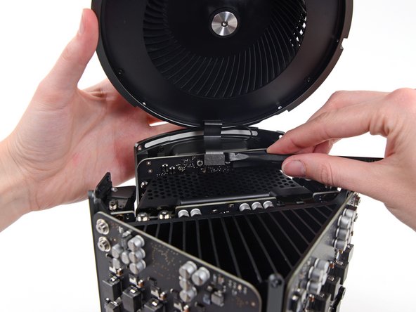
    • 한 손으로 팬 어셈블리를 받치면서 팬 케이블 브래킷에서 T8 고정 나사 두 개를 풀어주세요.

    • 이 나사들은 Mac Pro에 고정되어 있습니다. Mac Pro에서 이 나사들을 분리하려고 시도하지 마세요.

    On my Mac Pro (assembled mid-2017) these are T8 screws. In fact, there were no T7 screws anywhere in my machine.

    mark33 - 답글

    There was no bracket on top of the cable at all, so I got a bit confused, so I had to skip step 5 and 6.

    Rakesh - 답글

    On my machine, a TR7 worked to remove them due to the weird angle.

    Wilson Gaberino - 답글

  6. Mac Pro Late 2013 로직 보드 교체하기: 6 단계, 이미지 1/1
    • 핀셋을 사용하여 팬 케이블 브래킷을 팬 어셈블리에서 분리하세요.

  7. Mac Pro Late 2013 로직 보드 교체하기: 7 단계, 이미지 1/2 Mac Pro Late 2013 로직 보드 교체하기: 7 단계, 이미지 2/2
    • 스퍼저의 평평한 끝을 사용하여 팬 어셈블리 리본 케이블을 IO 보드에서 연결 해제하세요.

  8. Mac Pro Late 2013 로직 보드 교체하기: 8 단계, 이미지 1/1
    • 팬 어셈블리의 안테나 케이블을 IO 보드에서 연결 해제하세요.

    • 팬 어셈블리를 Mac Pro에서 분리하세요.

    You don't have to remove the fan assy to do the steps below. They can be done with the fan assy still attached.

    Fat Mango - 답글

  9. Mac Pro Late 2013 로직 보드 교체하기, 하단 케이스: 9 단계, 이미지 1/3 Mac Pro Late 2013 로직 보드 교체하기, 하단 케이스: 9 단계, 이미지 2/3 Mac Pro Late 2013 로직 보드 교체하기, 하단 케이스: 9 단계, 이미지 3/3
    • Mac Pro를 180도 거꾸로 뒤집으세요.

    • 하부 케이스 외부 둘레에서 5.1mm T10 나사 다섯 개를 풀어주세요.

  10. Mac Pro Late 2013 로직 보드 교체하기: 10 단계, 이미지 1/2 Mac Pro Late 2013 로직 보드 교체하기: 10 단계, 이미지 2/2
    • Mac Pro에서 하단 케이스를 조심히 들어올려 분리하세요.

  11. Mac Pro Late 2013 로직 보드 교체하기, 상호 연결 보드: 11 단계, 이미지 1/2 Mac Pro Late 2013 로직 보드 교체하기, 상호 연결 보드: 11 단계, 이미지 2/2
    • 스퍼저의 평평한 끝으로 비틀어서 그래픽 카드 데이터 연결을 해제 하세요.

  12. Mac Pro Late 2013 로직 보드 교체하기: 12 단계, 이미지 1/3 Mac Pro Late 2013 로직 보드 교체하기: 12 단계, 이미지 2/3 Mac Pro Late 2013 로직 보드 교체하기: 12 단계, 이미지 3/3
    • 다른 쪽도 조심히 분리하세요.

    • 커텍터를 위로 뒤집어 그래픽 카드에 방해가 되지 않게 하세요.

    • 이 절차를 다른 그래픽 카드에도 반복하세요.

  13. Mac Pro Late 2013 로직 보드 교체하기: 13 단계, 이미지 1/1
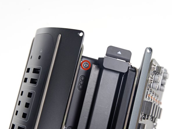
    • 상호 연결 보드를 방열판에 고정하는 6.0mm T8 Torx 나사 두 개를 풀어주세요.

    These are actually 6.0mm T8 Torx Screws. 12/07/2016.

    Todd - 답글

    Ended up being T9 screws for me.

    Nathaniel Wilson - 답글

    On my Mac Pro (assembled mid-2017) these are T8 screws. In fact, there were no T7 screws anywhere in my machine.

    mark33 - 답글

    These are T8 screws in my 2013 Mac Pro.

    Sangers - 답글

    T8 screws for me, i did and edit to this step

    Steve McGinn - 답글

    Ended up being T15 screws on my machine

    Spencer Curtis - 답글

  14. Mac Pro Late 2013 로직 보드 교체하기: 14 단계, 이미지 1/3 Mac Pro Late 2013 로직 보드 교체하기: 14 단계, 이미지 2/3 Mac Pro Late 2013 로직 보드 교체하기: 14 단계, 이미지 3/3
    • 로직 보드의 슬롯 연결에서 상호 연결 보드를 똑바로 위로 조심히 들어 올리 세요.

    • 한쪽을 들어 올린 후 다른 쪽을 들어 올리는 것이 좋습니다.

    • 상호 연결 보드는 여전히 IO 보드에 연결되어 있으므로, 아직 Mac Pro에서 분리하려 하지 마세요.

  15. Mac Pro Late 2013 로직 보드 교체하기: 15 단계, 이미지 1/2 Mac Pro Late 2013 로직 보드 교체하기: 15 단계, 이미지 2/2
    • 상호 연결 보드를 위로 젖히고 뒤집어서 IO 보드 데이터 케이블을 드러내세요.

    • 스퍼저의 평평한 끝으로 비틀고 벌려서 IO 보드 데이터 케이블 한 쪽을 분리하세요.

  16. Mac Pro Late 2013 로직 보드 교체하기: 16 단계, 이미지 1/2 Mac Pro Late 2013 로직 보드 교체하기: 16 단계, 이미지 2/2
    • 스퍼저의 평평한 끝으로 IO 보드 데이터 케이블의 다른 쪽을 분리하세요.

    • 케이블을 구부려 Mac Pro에서 상호 연결 보드를 분리하세요.

  17. Mac Pro Late 2013 로직 보드 교체하기, 전원 공급 장치 어셈블리: 17 단계, 이미지 1/1
    • Mac Pro를 다시 뒤집어 평평한 표면에 조심히 놓으세요.

    • 방열판 모서리와 상호 연결 보드에 부착되는 두 개의 standoff/스탠드오프 나사 기둥에 Mac Pro를 놓는 것이 좋습니다.

  18. Mac Pro Late 2013 로직 보드 교체하기: 18 단계, 이미지 1/2 Mac Pro Late 2013 로직 보드 교체하기: 18 단계, 이미지 2/2
    • 전원 공급 장치 케이지 측면에서 3.6mm T5 Torx 나사 두 개를 (각 측면에 하나씩) 풀어주세요.

    those are t4 screws in my mac

    Andrzej Kiryluk - 답글

    T4s on mine, as well

    rwcinmsp - 답글

  19. Mac Pro Late 2013 로직 보드 교체하기: 19 단계, 이미지 1/1
    • 전원 공급 장치 상단에서 전원 공급 장치 케이지를 분리해주세요.

    • 이 케이지를 제거함으로써, 전원 공급 장치 내부의 부품이 노출됩니다. 전원 공급 장치 내부 부품 또는 회로를 만지지 않도록 주의하세요.

    • 전원 공급 장치 내부 부품이 망가질 수 있으니, 전원 공급 장치 내부로 나사나 도구를 떨어뜨리지 않도록 주의하세요.

  20. Mac Pro Late 2013 로직 보드 교체하기: 20 단계, 이미지 1/1
    • Mac Pro에 전원 공급 장치 어셈블리를 고정하는 5.5mm T8 Torx 나사 네 개를 풀어주세요.

  21. Mac Pro Late 2013 로직 보드 교체하기: 21 단계, 이미지 1/1
    • 전원 공급 장치 어셈블리를 Mac Pro에서 분리하세요.

  22. Mac Pro Late 2013 로직 보드 교체하기, 로직 보드: 22 단계, 이미지 1/1
    • 5.5mm T8 Torx 나사 두 개를 풀어주세요.

    Il est possible de les retirer aussi des le début une fois le “fond” rond du Mac pro retiré

    Chris - 답글

    Step 22 when reassembling, it helps not to fully tighten until you put the screws in from step 20.

    Mike Sheedy - 답글

  23. Mac Pro Late 2013 로직 보드 교체하기: 23 단계, 이미지 1/1
    • CPU 방열판 브래킷에서 12.8mm T10 Torx 나사 네 개를 풀어주세요.

    • 여덟 개의 나사 중 외부 네 개만 풀어주세요.

    I cannot unscrew one of those because I appears that one of the elements in wich it is screwd underneath is loose and moving along with the screw, making this operation impossible. Anyone had this issue ?? Any solution ??

    benjaminmonnoyeur - 답글

    I had the same problem. These screws go into threaded inserts, which in turn are screwed into the heatsink. Both have threadlocker compound applied. So the threaded insert’s threadlocker gives up first, and the threaded insert unscrews from the heatsink. Remove all 4 screws, then with a pair of needle nose pliers, hemostat, or thin 7mm wrench, hold the insert steady and unscrew the screw from it.

    Chuck Fry - 답글

    Could I remove these screws and re-screw? I worry that remove them but I can’t re-use them?

    timmy123 -

    I had that problem, too, and I did it like Chuck Fry, with a thin wrench. Unfortunately one threaded insert was so tight that I slipped and a capacitor broke off. Can someone tell me what kind of capacitor I need? I can't find anything under the name listed above the capacitor. Thank you.

    Steph - 답글

    A way to avoid this situation is to ease the tension on the spring slowly and rotate the loosening of four screws a few turns at a time – when the tension is released equally the threaded inserts are more likely to stay in place.

    Steve Esser - 답글

    I had 2 of those double sided screws stuck like that. I carefully removed them from the motherboard using a small vice grip to hold one side, and a torx on the other. Then reinstalled them using locktite compound. Make sure the heat sink is flush to the motherboard in the same way that you found it, or the assembly will not fit back in the case correctly, indicating the CPU may not be securely attached. The result may be that you think you killed your mac when you turn in on again and just hear the fan spinning like crazy but no chime or boot sequence. If that happens, go back in, reset the double sided screws, and make sure the heatsink is flush. Worked for me.

    Sili_pepper - 답글

  24. Mac Pro Late 2013 로직 보드 교체하기: 24 단계, 이미지 1/2 Mac Pro Late 2013 로직 보드 교체하기: 24 단계, 이미지 2/2
    • 이 시점에서, 로직 보드는 서멀 컴파운드에 의해 방열판에 고정되어 있습니다.

    • 로직 보드를 방열판에서 분리하려면 스퍼저로 살살 들어 올려야 할 수도 있습니다.

    • 로직 보드를 구부리거나 부러지지 않도록 각별히 주의하세요.

    • 방열판에서 로직 보드를 분리해주세요.

  25. Mac Pro Late 2013 로직 보드 교체하기: 25 단계, 이미지 1/2 Mac Pro Late 2013 로직 보드 교체하기: 25 단계, 이미지 2/2
    • CPU 방열판 브래킷에서 내부 12.8mm T10 Torx 나사 네 개를 풀어주세요.

    • CPU 방열판 브래킷을 분리하세요.

    On my Mac Pro (assembled mid-2017) these screws are covered with a black sticker presumably to indicate tampering. If you did not know they were screws it would not be obvious. You have to just put the T10 driver right in the center and start turning; it quickly breaks through the sticker.

    mark33 - 답글

    Oh man. Thanks so much for that comment! I would have tried to use pliers!

    Trevor Standley - 답글

    Also remember to support the CPU (On the other side) while removing these screws. Mine CPU fell out from the other side while loosening.

    Daniel Wood - 답글

    On my MacPro there are no screws here. On the backside the place where the back of the screws should be are covered with stickers, but removing the stickers simply reveals a rivet. There’s no screw and seemingly no way to remove the CPU.

    rsproductions - 답글

    Je confirme, un sceau plastique noir protège les 4 vis. Il faut percer et dévisser au centre avec t9 pour moi

    Chris - 답글

    Wow, glad I clicked comments. I had no clue about the sticker. I was about to use some kind of something to get them out 😂

    Marc Kinnear - 답글

  26. Mac Pro Late 2013 로직 보드 교체하기: 26 단계, 이미지 1/1
    • 두 번째 방열판 브래킷을 분리하세요.

  27. Mac Pro Late 2013 로직 보드 교체하기: 27 단계, 이미지 1/2 Mac Pro Late 2013 로직 보드 교체하기: 27 단계, 이미지 2/2
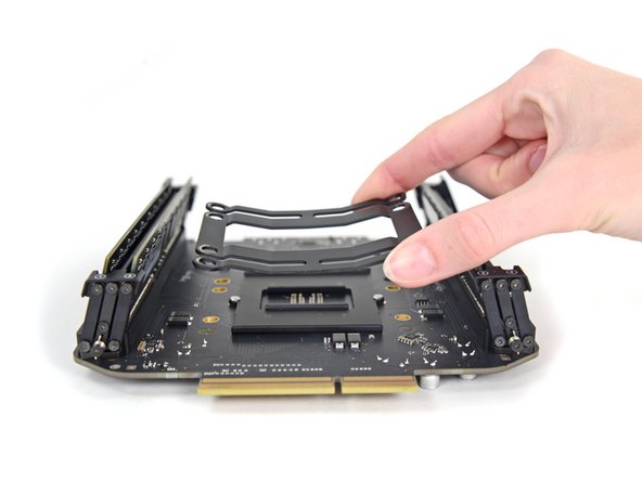
    • CPU와 브래킷에서 로직보드를 들어올려 분리하세요.

    • 재조립할 떄, CPU에 묻어있는 서멀 그리스를 깨끗히 닦고 다시 발라야 합니다.

    • 우리는 서멀 컴파운드를 쉽게 다시 바를수 있는 서멀 그리스 안내서를 가지고 있습니다.

    There is one import piece of information when replacing or upgrading these processors. There are two possible orientations and only one is correct (correct me if I’m wrong!). There’s a small arrow on one corner of the processor that needs to be aligned to the correct side. Just match the orientation of the original processor - this can be difficult or easy to overlook since the tiny alignment arrow is usually covered with thermal paste. Clean the Thermal paste off the old processor before you remove it to see the correct alignment.

    Steve Esser - 답글

결론

기기를 재조립하려면, 이 지침들을 역순으로 수행하세요.

다른 11명이 해당 안내서를 완성하였습니다.

다음 번역가들에게 특별히 감사 드립니다:

en ko

90%

이 번역자 분들은 저희가 세상을 수리하는데 동참해 주시는 분입니다! 기여하시겠습니까?
번역 시작하기 ›

Andrew Optimus Goldheart

회원 가입일: 10/17/09

502,990 평판

안내서 407개 작성하였습니다

iFixit iFixit 회원

Staff

135 회원들

안내서 17,141개 작성하였습니다

댓글 한 개

The RAM/CPU board is only attached to the thermal core around the processor area. This means seating RAM modules can flex the board (which has no support under the RAM sockets) so take extra care seating RAM modules.

john gilchrist - 답글

댓글 쓰기

조회 통계:

24 시간 전: 4

7일 전: 28

30일 전: 118

전체 시간: 15,162