이 버전에는 잘못된 편집 사항이 있을 수 있습니다. 최신 확인된 스냅샷으로 전환하십시오.
필요한 것
-
-
P5 펜타로브 드라이버를 사용하여 하난 케이스를 고정하는 다음 길이의 나사 10개를 풀어주세요:
-
9mm 나사 두 개
-
2.6mm 나사 여덟 개
-
-
이 단계는 번역되지 않았습니다. 번역을 도와주십시오
-
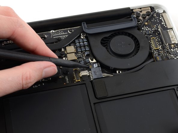
Use the flat end of a spudger to pry the I/O board cable connector up out of its socket on the I/O board.
-
-
이 단계는 번역되지 않았습니다. 번역을 도와주십시오
-
Carefully peel the I/O board cable from the adhesive securing it to the top of the fan.
-
-
이 단계는 번역되지 않았습니다. 번역을 도와주십시오
-
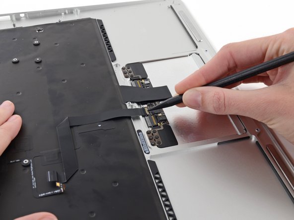
While gently pulling the I/O board cable upward near its connection to the logic board, use the flat end of a spudger to pry up on alternating sides of the connector to help "walk" it out of its socket.
-
Remove the I/O board cable.
-
-
이 단계는 번역되지 않았습니다. 번역을 도와주십시오
-
Use the tip of a spudger to carefully flip up the retaining flap on the fan cable ZIF socket.
-
-
이 단계는 번역되지 않았습니다. 번역을 도와주십시오
-
Remove the following three screws securing the fan to the upper case:
-
One 5.2 mm T5 Torx screw
-
One 3.3 mm T5 Torx screw
-
One 4.4 mm T5 Torx screw with a short head
-
-
이 단계는 번역되지 않았습니다. 번역을 도와주십시오
-
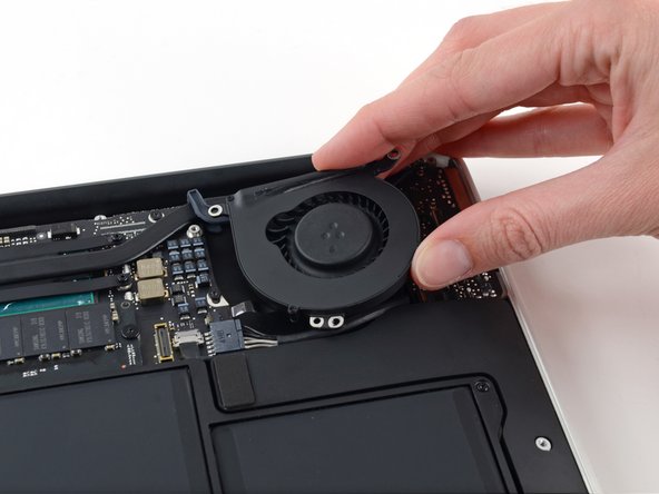
Lift the fan from the I/O board side and pull it free from the upper case.
-
Removing the fan will also disconnect the fan ribbon cable. Be careful not to snag it.
-
-
이 단계는 번역되지 않았습니다. 번역을 도와주십시오
-
Disconnect the I/O board by pulling its power cable away from its socket on the logic board.
-
-
이 단계는 번역되지 않았습니다. 번역을 도와주십시오
-
Use the flat end of a spudger to pry the left speaker cable connector up and out of its socket on the I/O board.
-
-
이 단계는 번역되지 않았습니다. 번역을 도와주십시오
-
Use the tip of a spudger to carefully flip up the retaining flap on the microphone ribbon cable ZIF socket.
-
-
이 단계는 번역되지 않았습니다. 번역을 도와주십시오
-
Remove the single 4.1 mm T5 Torx screw securing the I/O board to the upper case.
-
-
-
이 단계는 번역되지 않았습니다. 번역을 도와주십시오
-
Gently de-route the camera cable from its notch on the I/O board and push it out of the way with the tip of a spudger.
-
-
이 단계는 번역되지 않았습니다. 번역을 도와주십시오
-
Lift the I/O board from the logic board side and pull it free from the upper case.
-
Removing the I/O board will also disconnect the microphone ribbon cable. Be careful not to snag it.
-
-
-
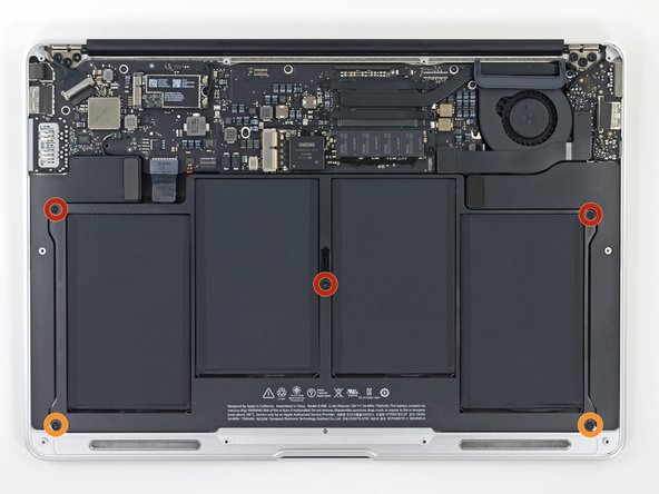
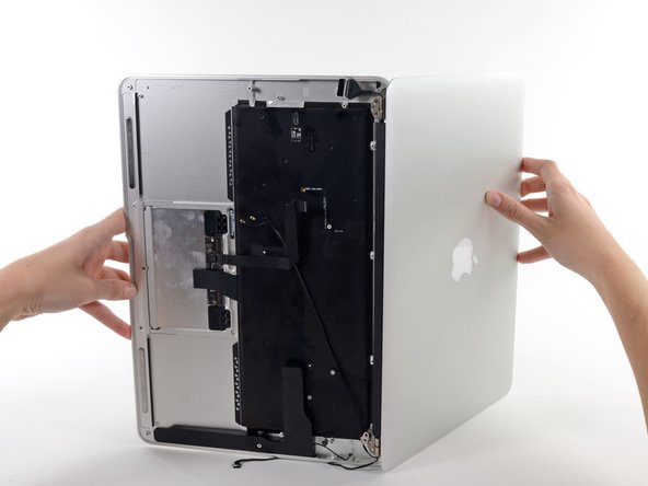
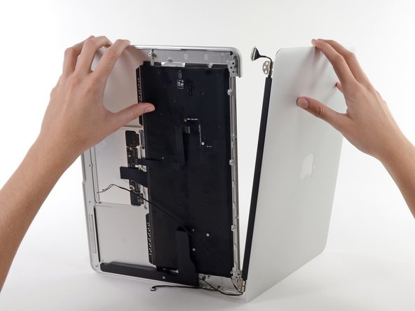
배터리를 로직 보드에 가장 가까운 가장자리에서 들어 올려 상단 케이스에서 분리하세요.
-
배터리를 100%까지 충전한 다음 계속해서 2시간 이상 충전하세요. 그런 다음 플러그를 뽑고 정상적으로 사용하여 배터리를 방전시키세요. 배터리 부족 경고가 표시되면 작업을 저장하고 배터리 부족으로 인해 노트북이 절전 모드로 전환될 때까지 노트북을 계속 켜두세요. 5시간 이상 기다린 다음 중단 없이 노트북을 100%까지 충전하세요.
-
새 배터리를 설치한 후 비정상적인 작동이나 문제가 발견되면 MacBook의 SMC를 재설정해야 할 수 있습니다.
-
-
이 단계는 번역되지 않았습니다. 번역을 도와주십시오
-
Grab the plastic pull tab secured to the display data cable lock and rotate it towards the top side of the computer.
-
-
이 단계는 번역되지 않았습니다. 번역을 도와주십시오
-
Use the flat end of a spudger to pry both antenna cable connectors up and off their sockets on the AirPort/Bluetooth card.
-
-
이 단계는 번역되지 않았습니다. 번역을 도와주십시오
-
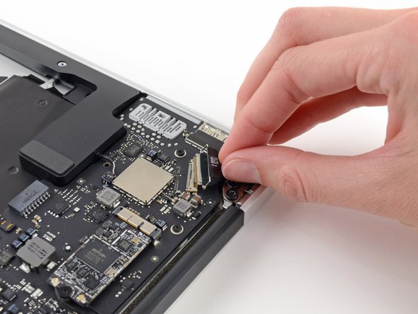
Disconnect the camera cable connector with the tip of a spudger.
-
Pull the camera cable parallel to the face of the I/O board toward the front edge of the Air to disconnect it from its socket.
-
-
이 단계는 번역되지 않았습니다. 번역을 도와주십시오
-
Use the tip of a spudger or your fingernail to flip up the retaining flap on the trackpad ribbon cable ZIF socket.
-
Pull the trackpad ribbon cable straight out of its socket toward the front edge of the Air.
-
-
이 단계는 번역되지 않았습니다. 번역을 도와주십시오
-
Use the tip of a spudger to flip up the retaining flap on the keyboard backlight ribbon cable ZIF socket.
-
Use your spudger to gently pull the keyboard backlight ribbon cable out of its socket.
-
-
이 단계는 번역되지 않았습니다. 번역을 도와주십시오
-
Use the flat end of a spudger to pry the right speaker cable connector up and out of its socket on the logic board.
-
-
이 단계는 번역되지 않았습니다. 번역을 도와주십시오
-
Remove the six 6.3 mm T5 Torx screws securing the logic board to the upper case.
-
-
이 단계는 번역되지 않았습니다. 번역을 도와주십시오
-
Remove the inner two 4.9 mm T8 Torx screws securing the antenna cable retainer and left clutch hinge to the upper case.
-
-
이 단계는 번역되지 않았습니다. 번역을 도와주십시오
-
Push the antenna cable retainer away slightly and remove the 3 mm T5 Torx screw securing the end of the heat sink to the upper case.
-
-
이 단계는 번역되지 않았습니다. 번역을 도와주십시오
-
Slide the flat end of a spudger under the right speaker from the end nearest the hinge to the front edge of the Air to loosen the adhesive.
-
Remove the right speaker from the upper case.
-
-
이 단계는 번역되지 않았습니다. 번역을 도와주십시오
-
Carefully remove the logic board assembly from the upper case, minding any cables that may get caught.
-
Keep loose cables clear of the board so they aren't caught under it.
-
Make sure the antenna cables are inserted into their respective notches, as highlighted in the second picture.
-
-
이 단계는 번역되지 않았습니다. 번역을 도와주십시오
-
Remove the inner two 5.6 mm T8 Torx screws securing the right display hinge to the upper case.
-
-
이 단계는 번역되지 않았습니다. 번역을 도와주십시오
-
While holding the Air steady, remove the remaining 5.6 mm T8 Torx screw from the display bracket.
-
-
이 단계는 번역되지 않았습니다. 번역을 도와주십시오
-
Remove the last 5.6 mm T8 Torx screw securing the display to the upper case.
-
-
이 단계는 번역되지 않았습니다. 번역을 도와주십시오
-
Open the Air slowly until the hinges slide out of their notches.
-
Once the two display hinges have cleared the upper case, remove the display and set it aside.
-
-
이 단계는 번역되지 않았습니다. 번역을 도와주십시오
-
Use the flat end of a spudger to pry the left speaker off the adhesive securing it to the upper case.
-
Remove the left speaker from the upper case.
-
-
이 단계는 번역되지 않았습니다. 번역을 도와주십시오
-
Use the flat end of a spudger to pry the microphone off the adhesive securing it to the left side of the upper case.
-
If needed, apply a little heat from an iOpener or hairdryer to soften the adhesive.
-
Remove the microphone from the upper case.
-
-
이 단계는 번역되지 않았습니다. 번역을 도와주십시오
-
Use the tip of a spudger or your fingernail to flip up the retaining flap on the trackpad ribbon cable ZIF socket.
-
Pull the trackpad ribbon cable straight out of its socket toward the rear edge of the Air.
-
-
이 단계는 번역되지 않았습니다. 번역을 도와주십시오
-
While carefully lifting the keyboard ribbon cable with one hand, use the tip of a spudger or your fingernail to flip up the retaining flap on the keyboard ribbon cable ZIF socket.
-
Pull the keyboard ribbon cable straight out of its socket toward the front edge of the Air.
-
-
이 단계는 번역되지 않았습니다. 번역을 도와주십시오
-
Remove the following seven screws:
-
Six 1.6 mm Phillips screws securing the trackpad to the upper case.
-
One 1.4 mm T5 Torx set screw from its tapped hole near the front edge of the upper case.
-
-
이 단계는 번역되지 않았습니다. 번역을 도와주십시오
-
Carefully lift the edge of the trackpad closest to the keyboard from its recess in the upper case by lifting it away from the brackets attached to the upper case.
-
Remove the trackpad from the upper case.
-
The upper case remains.
-


다른 14명이 해당 안내서를 완성하였습니다.

댓글 4개
Excellent guide. As there was no guide for mainboard replacement I used this one up to step 30, perhaps there should be a guide? The most difficult part for me was getting the rubber fan gasket to sit where it needed to during reassembly, perhaps a detail photo of this when the PCB is floating would be a benefit. I also had another small rubber piece come loose from somewhere and was unable to determine where it was supposed to live. It was about 1.5 cm long, and had an extruded channel in it, like perhaps it was supposed to protect and edge or a cable… seemed to fall off from somewhere on the LCD connector side of the board, but I don’t see it in any of the photos included and nothing was obvious.
I used this as a teardown and then in reverse a rebuild guide. My mac was water damaged and I replaced the logic board using this guide. And it worked! Thanks so much to the author