이 버전에는 잘못된 편집 사항이 있을 수 있습니다. 최신 확인된 스냅샷으로 전환하십시오.
필요한 것
-
-
P5 펜타로브 드라이버를 사용하여 하난 케이스를 고정하는 다음 길이의 나사 10개를 풀어주세요:
-
9mm 나사 두 개
-
2.6mm 나사 여덟 개
-
-
이 단계는 번역되지 않았습니다. 번역을 도와주십시오
-
Use the flat end of a spudger to pry the I/O board cable connector up out of its socket on the I/O board.
-
-
이 단계는 번역되지 않았습니다. 번역을 도와주십시오
-
Carefully peel the I/O board cable from the adhesive securing it to the top of the fan.
-
-
이 단계는 번역되지 않았습니다. 번역을 도와주십시오
-
While gently pulling the I/O board cable upward near its connection to the logic board, use the flat end of a spudger to pry up on alternating sides of the connector to help "walk" it out of its socket.
-
Remove the I/O board cable.
-
-
이 단계는 번역되지 않았습니다. 번역을 도와주십시오
-
Use the tip of a spudger to carefully flip up the retaining flap on the fan cable ZIF socket.
-
-
이 단계는 번역되지 않았습니다. 번역을 도와주십시오
-
Remove the following three screws securing the fan to the upper case:
-
One 3.6 mm T5 Torx screw
-
One 2.7 mm T5 Torx screw
-
One 3.6 mm T5 Torx screw with a short head
-
-
-
이 단계는 번역되지 않았습니다. 번역을 도와주십시오
-
Lift the fan from the I/O board side and pull it free from the upper case.
-
Removing the fan will also disconnect the fan ribbon cable. Be careful not to snag it.
-
-
이 단계는 번역되지 않았습니다. 번역을 도와주십시오
-
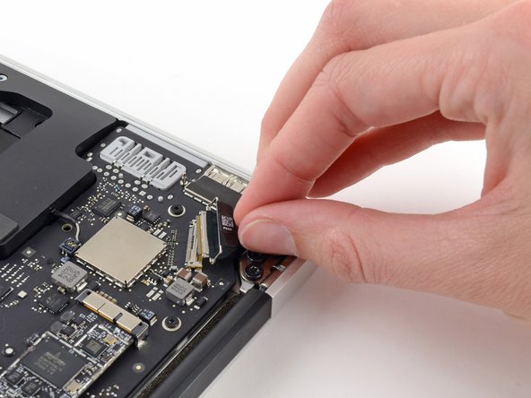
Disconnect the I/O board by pulling its power cable away from its socket on the logic board.
-
-
이 단계는 번역되지 않았습니다. 번역을 도와주십시오
-
Use the flat end of a spudger to pry the left speaker cable connector up and out of its socket on the I/O board.
-
-
이 단계는 번역되지 않았습니다. 번역을 도와주십시오
-
Use the tip of a spudger to carefully flip up the retaining flap on the microphone ribbon cable ZIF socket.
-
-
이 단계는 번역되지 않았습니다. 번역을 도와주십시오
-
Remove the single 3.6 mm T5 Torx screw securing the I/O board to the upper case.
-
-
이 단계는 번역되지 않았습니다. 번역을 도와주십시오
-
Gently de-route the camera cable from its notch on the I/O board and push it out of the way with the tip of a spudger.
-
-
이 단계는 번역되지 않았습니다. 번역을 도와주십시오
-
Lift the I/O board from the logic board side and pull it free from the upper case.
-
Removing the I/O board will also disconnect the microphone ribbon cable. Be careful not to snag it.
-
-
이 단계는 번역되지 않았습니다. 번역을 도와주십시오
-
Use the flat end of a spudger to pry each of the antenna connectors up from their sockets on the AirPort/Bluetooth card.
-
-
이 단계는 번역되지 않았습니다. 번역을 도와주십시오
-
Disconnect the camera cable connector with the tip of a spudger.
-
Pull the camera cable parallel to the face of the I/O board toward the front edge of the Air to disconnect it from its socket.
-
-
이 단계는 번역되지 않았습니다. 번역을 도와주십시오
-
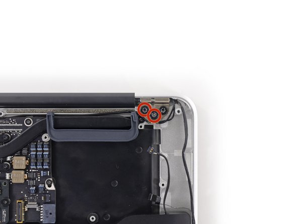
Remove the inner four (two on each side) 4.9 mm T8 Torx screws securing the right and left display hinges to the upper case.
-
-
이 단계는 번역되지 않았습니다. 번역을 도와주십시오
-
Gently de-route the antenna cables out of the channel cut into the upper case.
-
-
이 단계는 번역되지 않았습니다. 번역을 도와주십시오
-
While holding the Air steady, remove the remaining 4.9 mm T8 Torx screw from the left display bracket.
-
-
이 단계는 번역되지 않았습니다. 번역을 도와주십시오
-
Remove the last 4.9 mm T8 Torx screw securing the display to the upper case.
-
-
이 단계는 번역되지 않았습니다. 번역을 도와주십시오
-
Open the Air slightly to allow room for the hinges to slide out of their notches.
-
Push the upper case slightly toward the display assembly, then push it back from the hinges.
-
Once the two display hinges have cleared the upper case, remove the display and set it aside.
-


다른 77명이 해당 안내서를 완성하였습니다.

댓글 17개
Just a reminder that you DO NOT want to touch the battery with your hands or a screw driver you can compromise the integrity of the battery and possibly cause a thermal event. Always use proper battery cover kit.
When reassembling the device, keep in mind that the holes in the hinges are relatively big compared to the T8 screws, so there will be a certain play. Check if display and body are in line when the MacBook is closed, then tighten the screws.
When I noticed this (also similar issue when installing the trackpad), I thought "what an inferior engineering for such an expensive product".