이 버전에는 잘못된 편집 사항이 있을 수 있습니다. 최신 확인된 스냅샷으로 전환하십시오.
필요한 것
-
이 단계는 번역되지 않았습니다. 번역을 도와주십시오
-
Use a coin or spudger to rotate the battery-locking screw 90 degrees clockwise.
-
-
이 단계는 번역되지 않았습니다. 번역을 도와주십시오
-
Unscrew the three evenly-spaced Phillips screws from along the rear wall of the battery compartment.
-
-
이 단계는 번역되지 않았습니다. 번역을 도와주십시오
-
Grasp the right end of the L-shaped memory cover, then pull it towards you so it clears the battery compartment opening.
-
Lift the memory cover up and out of the computer.
-
-
이 단계는 번역되지 않았습니다. 번역을 도와주십시오
-
Remove the following 3 screws:
-
One 11 mm Phillips#00 in the middle of the lower case. (Head: 5mm dia. x .75mm thick)
-
Two 14.5 mm Phillips #00 (Head: 5mm dia. x .75mm thick)
-
-
이 단계는 번역되지 않았습니다. 번역을 도와주십시오
-
Remove the following 3 screws from the rear wall of the battery compartment:
-
One 3 mm Phillips #0. (Head: 2.75 mm. dia.)
-
Two 4 mm Phillips #0 on the either side. (Head: 2.75mm dia.)
-
-
이 단계는 번역되지 않았습니다. 번역을 도와주십시오
-
Remove the two Phillips screws from either side of the right wall of the battery compartment (not the ones closest to the battery connector).
-
Two 6.25 mm Phillips #000. (Head: 4 mm. dia. x .5mm thick)
-
-
이 단계는 번역되지 않았습니다. 번역을 도와주십시오
-
Remove the four indicated Phillips screws from the front wall of the battery compartment. When working from the left, remove the 2nd, 4th, 7th and 9th screws.
-
Four 3.25 mm Phillips #000. (Head: 4 mm. dia. x 4mm thick)
-
-
이 단계는 번역되지 않았습니다. 번역을 도와주십시오
-
Remove the following 4 screws from the back of the computer:
-
Two 11 mm Phillips #00, with Shank (2.2mm dia. x 2 mm len.) (Head: 3.2 mm. dia. x .5mm thick)
-
Two 7.25 mm Phillips #00, with Shank (2mm dia. x 3.75 mm len.) (Head: 3.2 mm. dia. x .5mm thick)
-
-
이 단계는 번역되지 않았습니다. 번역을 도와주십시오
-
Remove the two Phillips screws from the optical drive (right) side of the computer:
-
Two 5.2 mm Phillips #00, with shank (2.3mm dia. x 3.25 mm len.) (Head: 3.2 mm. dia. x .5mm thick)
-
-
이 단계는 번역되지 않았습니다. 번역을 도와주십시오
-
Use a plastic opening tool, an expired plastic credit, or a similarly-thick card to pry up on the upper case, starting in the upper-left corner and working around to the front of the computer.
-
-
이 단계는 번역되지 않았습니다. 번역을 도와주십시오
-
While holding up the upper case, pull up the black tab on the connector end of the silver ribbon cable away from the connector's socket on the logic board.
-
-
-
이 단계는 번역되지 않았습니다. 번역을 도와주십시오
-
Disconnect the MagSafe board cable from the logic board by pulling the snap-in connector out (to the right).
-
-
이 단계는 번역되지 않았습니다. 번역을 도와주십시오
-
Remove the single 9 mm Phillips screw securing the left speaker to the lower case.
-
Lift the left speaker out of its housing and set it to the side.
-
-
이 단계는 번역되지 않았습니다. 번역을 도와주십시오
-
Remove the following 3 screws:
-
Two 7.5 mm Phillips from either end of the left I/O frame.
-
One 9 mm Phillips from the middle of the left I/O frame.
-
Remove the small black plastic spacer at the bottom of the left I/O frame.
-
-
이 단계는 번역되지 않았습니다. 번역을 도와주십시오
-
Lift the left I/O frame up and out of the computer. Pay attention to the thin metal EMI fingers, as they may catch as you remove the left I/O frame.
-
-
이 단계는 번역되지 않았습니다. 번역을 도와주십시오
-
Use a spudger to move the gray display data and black speaker cables to the right. This will reveal a silver screw securing the fan housing to the lower case.
-
-
이 단계는 번역되지 않았습니다. 번역을 도와주십시오
-
Peel up the small black rubber cover from the right side of the heat sink.
-
-
이 단계는 번역되지 않았습니다. 번역을 도와주십시오
-
Disconnect the black fan connector and two temperature sensor connectors from the logic board by pulling/prying them directly up.
-
-
이 단계는 번역되지 않았습니다. 번역을 도와주십시오
-
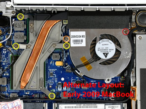
Remove the following 6 screws:
-
One 3 mm Phillips on the right side of the fan.
-
One 6 mm Phillips on the left side of the fan.
-
Four 9 mm Phillips securing the heat sink to the lower case.
-
-
이 단계는 번역되지 않았습니다. 번역을 도와주십시오
-
Hold the heat sink with one hand and the fan with your other hand, and lift the heat sink and fan assembly out of the computer. The fan is attached to the heat sink only with a strip of black felt tape, so be sure to remove both parts as a unit.
-
-
이 단계는 번역되지 않았습니다. 번역을 도와주십시오
-
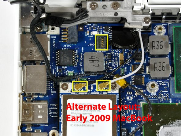
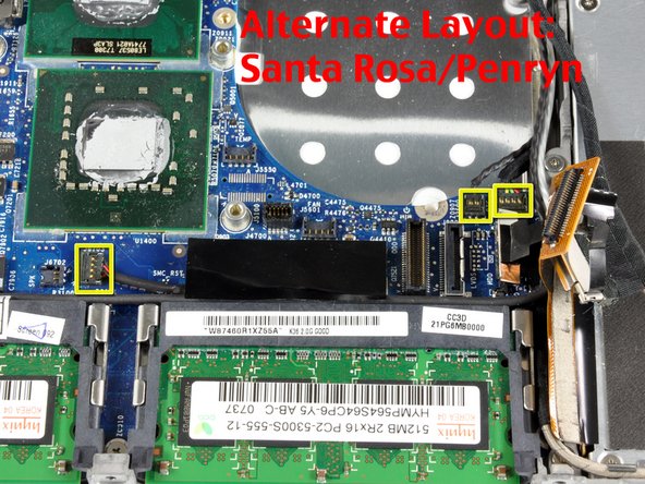
Disconnect the three antenna cables from the Airport card, and the black inverter cable from the logic board.
-
-
이 단계는 번역되지 않았습니다. 번역을 도와주십시오
-
Remove the following 2 screws from the Airport card:
-
One 3 mm Phillips from the left side.
-
One 8 mm (with a large 2 mm head) Phillips from the right side.
-
-
이 단계는 번역되지 않았습니다. 번역을 도와주십시오
-
Grasp the Airport card at its top and slide it toward the screen and out of the computer.
-
-
이 단계는 번역되지 않았습니다. 번역을 도와주십시오
-
Use a spudger to disconnect the left speaker connector from the logic board.
-
Lift the left speaker out of the computer.
-
-
이 단계는 번역되지 않았습니다. 번역을 도와주십시오
-
Disconnect the display data cable by pulling up on the black plastic pull-tab. If there is no pull-tab on the top of the connector, it may be helpful to use a spudger to disconnect this connector.
-
-
이 단계는 번역되지 않았습니다. 번역을 도와주십시오
-
Use a spudger to disconnect the speaker connector and bluetooth connector from the logic board.
-
-
이 단계는 번역되지 않았습니다. 번역을 도와주십시오
-
Use a spudger to carefully disconnect the microphone cable from the logic board. You'll want to work from side to side, and slowly wiggle the connector out of its socket.
-
-
이 단계는 번역되지 않았습니다. 번역을 도와주십시오
-
Deroute the microphone cable from the silver metal clip just above the right RAM slot.
-
-
이 단계는 번역되지 않았습니다. 번역을 도와주십시오
-
Use a spudger to carefully pry the battery connector up and disconnect it from the logic board.
-
-
이 단계는 번역되지 않았습니다. 번역을 도와주십시오
-
Remove the three 3 mm Phillips screws securing the logic board to the lower case.
-
-
이 단계는 번역되지 않았습니다. 번역을 도와주십시오
-
Lift the logic board up from the right side, and slide it up and out of the computer.
-


다른 5명이 해당 안내서를 완성하였습니다.
