이 버전에는 잘못된 편집 사항이 있을 수 있습니다. 최신 확인된 스냅샷으로 전환하십시오.
필요한 것
-
-
하단 케이스를 상단 케이스에 고정하는 다음 나사 열 개를 풀어주세요:
-
2.3mm P5 Pentalobe/펜타로브/별나사 두 개
-
3.0mm P5 Pentalobe/펜타로브/별나사 여덟 개
-
-
-
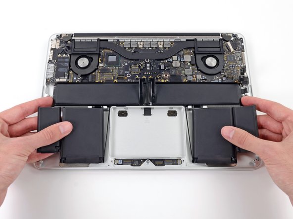
엄지 또는 손가락을 사용하여 SSD 트레이의 플라스틱 스프링 바를 구부려 기기 전면의 클립 두 개를 해제하세요.
-
스프링 바를 누르며 SSD 어셈블리를 기울여 공간에서 꺼내세요.
-
-
-
-
상단 케이스에서 배터리 전체를 들어 올리고 배터리를 분리하세요.
-
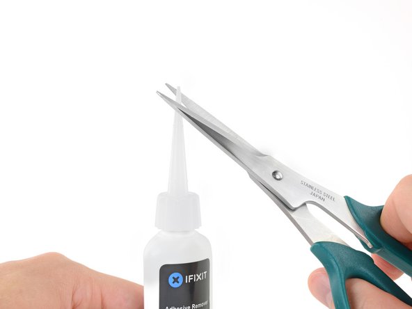
운이 좋으면 손가락으로 접착제 조각을 천천히 당겨 빼낼 수 있습니다.
-
그렇지 않으면 각 접착 부분을 약간의 접착제 제거제로 2-3분 동안 적신 다음 여는 픽 또는 키트의 다른 도구 중 하나로 긁어내야 합니다. 이는 꽤 많은 노력이 필요로 합니다. 인내심을 가지세요.
-
남아있는 모든 접착제 제거제를 닦아내고 MacBook Pro를 자연 건조할 때까지 몇 분 정도 기다리세요.
-
새로 설치한 배터리를 보정하세요: 배터리를 100% 충전한 다음 최소 두 시간 더 충전하세요. 그런 다음 플러그는 뽑고 정상적으로 사용하여 배터리를 방전하세요. 배터리 부족 경고가 나타나면 작업을 저장하고 배터리 부족으로 인해 절전 모드가 활성화될 때까지 노트북을 켜놓으세요. 최소한 5시간 이상을 기다리고 나서 노트북을 중단없이 100% 충전하세요.
-
-
이 단계는 번역되지 않았습니다. 번역을 도와주십시오
-
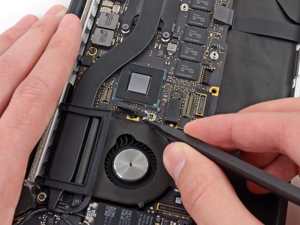
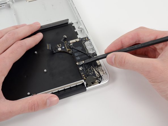
Use the tip of a spudger to push the edges of the I/O board connector straight out of its socket on the logic board.
-
-
이 단계는 번역되지 않았습니다. 번역을 도와주십시오
-
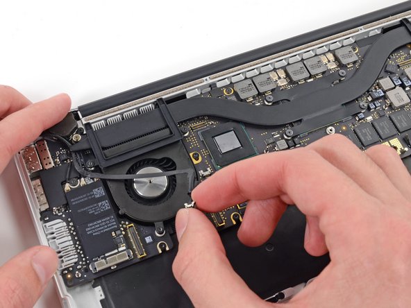
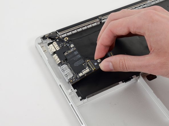
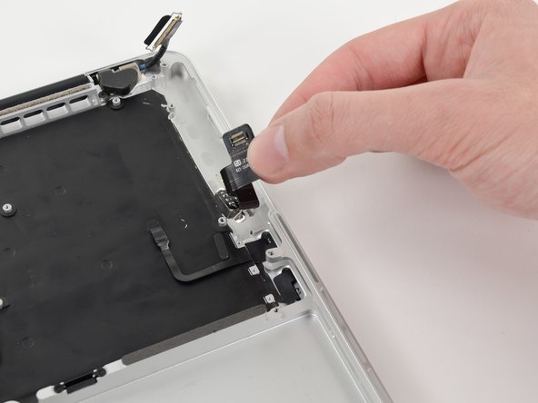
Use the tip of a spudger to push the iSight camera cable connector straight away from its socket on the logic board.
-
-
이 단계는 번역되지 않았습니다. 번역을 도와주십시오
-
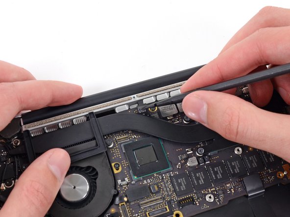
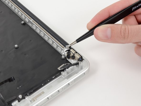
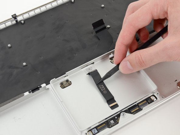
Wedge the flat end of a spudger underneath the keyboard backlight connector and the logic board.
-
Gently twist the flat end of a spudger upwards to pry the keyboard backlight connector up off its socket on the logic board.
-
-
이 단계는 번역되지 않았습니다. 번역을 도와주십시오
-
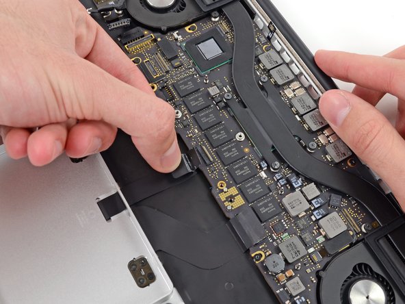
Use the tip of a spudger to flip up the retaining flap on the trackpad ribbon cable ZIF socket.
-
Grasp the plastic pull tab and pull the trackpad ribbon cable out of its socket.
-
-
이 단계는 번역되지 않았습니다. 번역을 도와주십시오
-
Use the tip of a spudger to flip up the retaining flap on the keyboard ribbon cable ZIF socket.
-
Grasp the plastic pull tab and pull the keyboard ribbon cable out of its socket.
-
-
이 단계는 번역되지 않았습니다. 번역을 도와주십시오
-
Use the tip of a spudger to flip up the retaining flap on the microphone ribbon cable ZIF socket.
-
Grasp the plastic pull tab and pull the microphone ribbon cable out of its socket.
-
-
이 단계는 번역되지 않았습니다. 번역을 도와주십시오
-
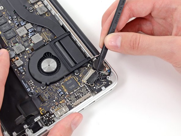
Use the tip of a spudger to rotate the pull tab secured to the display data cable lock toward the DC-In side of the computer.
-
-
이 단계는 번역되지 않았습니다. 번역을 도와주십시오
-
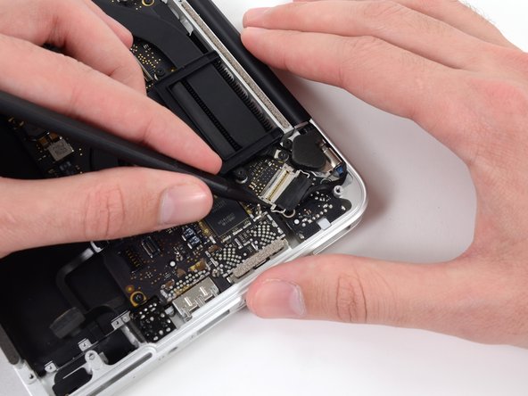
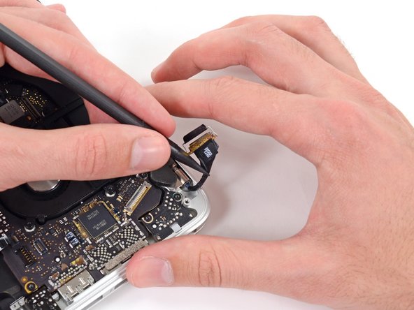
Gently push the edges of the display data cable connector away from its socket on the logic board.
-
Pull, but do not remove, the display data cable connector out of its socket and carefully move it out of the way.
-
-
이 단계는 번역되지 않았습니다. 번역을 도와주십시오
-
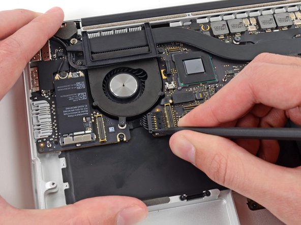
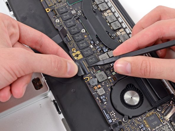
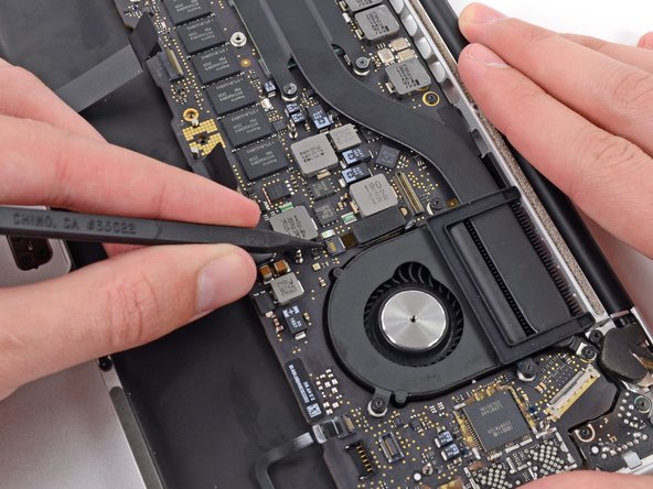
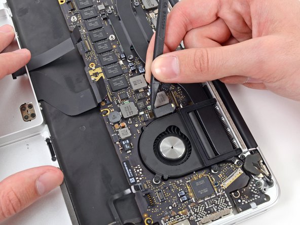
Use the tip of a spudger to flip up the retaining flap on the left fan ribbon cable ZIF socket.
-
Carefully pull the left fan ribbon cable out of its socket.
-
-
이 단계는 번역되지 않았습니다. 번역을 도와주십시오
-
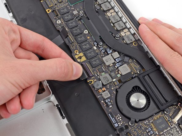
Move the left fan ribbon cable aside to reveal a hidden screw securing the logic board assembly to the upper case.
-
-
이 단계는 번역되지 않았습니다. 번역을 도와주십시오
-
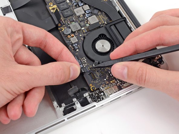
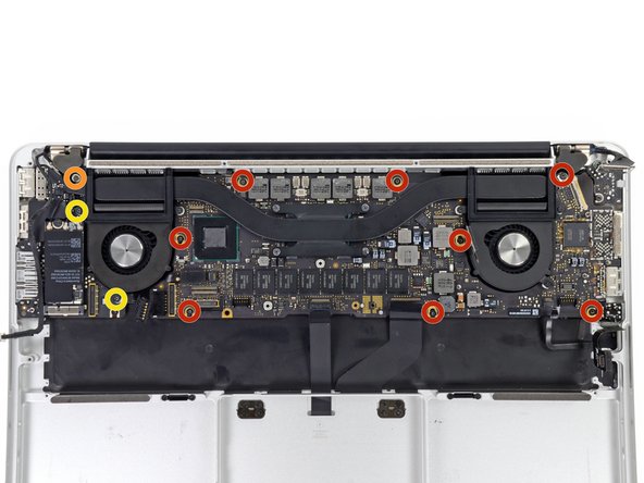
Remove the following screws securing the logic board to the upper case:
-
Eight 3.3 mm T5 Torx screws
-
One Phillips #00 screw
-
Two 3.1 mm T5 Torx screws
-
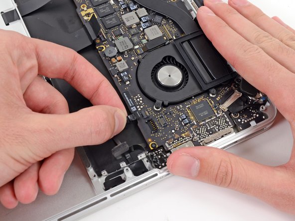
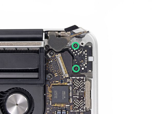
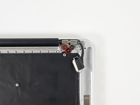
Remove two more screws, from the MagSafe DC-In board in the upper right corner (second image).
-
Two 3.4 mm T5 Torx screws
-
-
이 단계는 번역되지 않았습니다. 번역을 도와주십시오
-
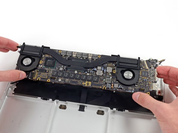
Carefully lift the logic board assembly from its left side and work it out of the upper case, minding any cables and the I/O ports that may get caught during removal.
-
Pull the right I/O port side of the logic board away from the side of the upper case and remove the logic board assembly.
-
-
이 단계는 번역되지 않았습니다. 번역을 도와주십시오
-
Use the flat end of a spudger to pry and disconnect the three antenna cable connectors from the AirPort board.
-
Connect the long-sleeved cable to the center socket.
-
The short-sleeved cable connects next to the screw.
-
The remaining cable has no sleeve, and connects in the last empty socket, next to the fan.
-
-
이 단계는 번역되지 않았습니다. 번역을 도와주십시오
-
Remove the following two screws securing the I/O board to the upper case:
-
One 3.53 mm T5 Torx screw
-
One 4.89 mm T8 Torx standoff screw
-
-
이 단계는 번역되지 않았습니다. 번역을 도와주십시오
-
Carefully pull and remove the I/O board away from its recess in the upper case.
-
-
이 단계는 번역되지 않았습니다. 번역을 도와주십시오
-
Remove the two 3.4 mm T5 Torx screws securing the headphone jack to the upper case.
-
-
이 단계는 번역되지 않았습니다. 번역을 도와주십시오
-
Use a pair of tweezers to lift the rubber hinge covers up off the right and left display hinges.
-
-
이 단계는 번역되지 않았습니다. 번역을 도와주십시오
-
Remove the 3.2 mm T5 Torx screws (one on each side) securing the aluminum hinge brackets to the upper case.
-
-
이 단계는 번역되지 않았습니다. 번역을 도와주십시오
-
Use a pair of tweezers to lift aluminum hinge brackets off the right and left display hinges.
-
-
이 단계는 번역되지 않았습니다. 번역을 도와주십시오
-
Remove the four inner 5.3 mm T8 Torx screws (two on each side) securing the display to the upper case.
-
-
이 단계는 번역되지 않았습니다. 번역을 도와주십시오
-
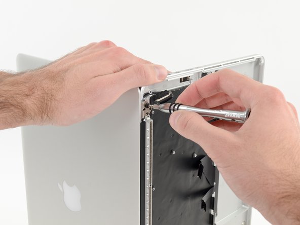
While holding the display and upper case together with your left hand, remove the remaining T8 Torx screw from the lower display bracket.
-
Remove the last remaining T8 Torx screw securing the display to the upper case.
-
-
이 단계는 번역되지 않았습니다. 번역을 도와주십시오
-
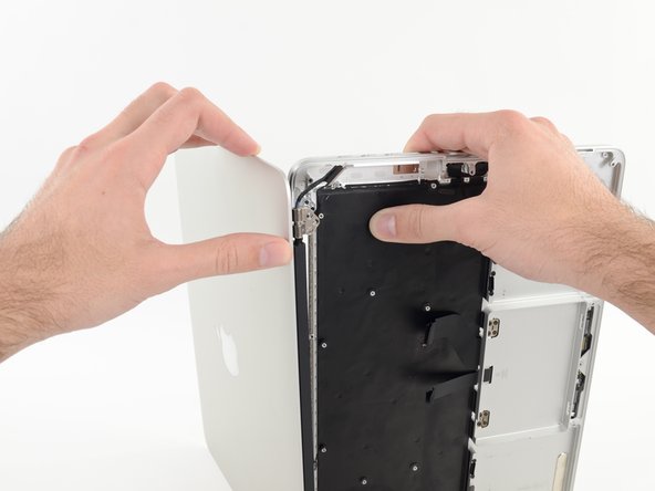
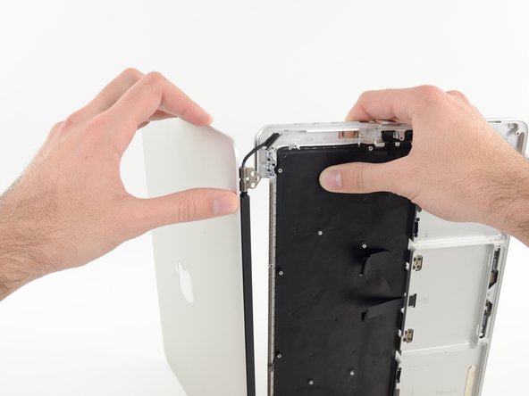
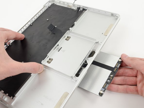
Grip both halves of the device, one in each hand.
-
Gently push forward on the bottom half of the device to detach it from the display assembly.
-
Carefully set each component aside, making sure to set down the lower half keyboard-side down.
-
-
이 단계는 번역되지 않았습니다. 번역을 도와주십시오
-
Remove the following screws securing the trackpad to the upper case:
-
Four 1.4 mm Phillips #000 screws
-
-
이 단계는 번역되지 않았습니다. 번역을 도와주십시오
-
Wedge the spudger between the trackpad ribbon cable and the upper case.
-
Run the spudger along the bottom to release the trackpad ribbon cable from the adhesive securing it to the upper case.
-
-
이 단계는 번역되지 않았습니다. 번역을 도와주십시오
-
Insert the tip of a spudger in between the trackpad ribbon cable and the upper case.
-
Carefully thread the trackpad ribbon cable out of the notch near the top of the SSD assembly cavity.
-
-
이 단계는 번역되지 않았습니다. 번역을 도와주십시오
-
Once the trackpad is free of the upper case, guide the trackpad ribbon cable through the slot cut in the upper case.
-
Remove the trackpad from the upper case.
-
-
이 단계는 번역되지 않았습니다. 번역을 도와주십시오
-
For this step, it is recommended to use a heat gun or hair dryer to soften the adhesive securing the microphone assembly to the upper case. You may be able to remove it without doing so, but will risk damaging the microphone cable.
-
With the heat gun set to low, heat the microphone assembly to loosen the adhesive attaching it to the upper case.
-
-
이 단계는 번역되지 않았습니다. 번역을 도와주십시오
-
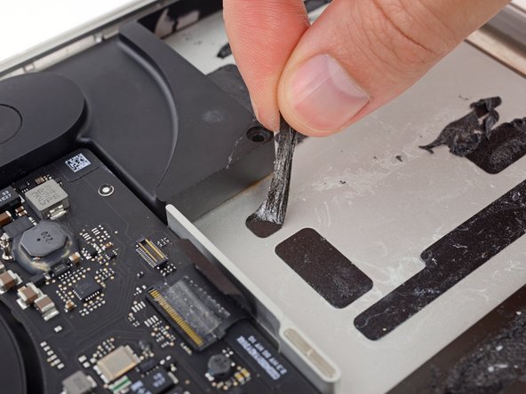
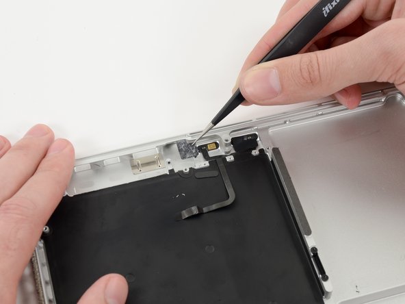
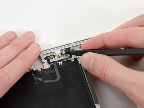
Use the tip of a spudger to remove the piece of tape covering one of two microphones.
-
Grasp the piece of tape with a pair of tweezers and remove it.
-
-
이 단계는 번역되지 않았습니다. 번역을 도와주십시오
-
Repeat the same procedure as the previous step to remove the tape covering the second microphone.
-
-
이 단계는 번역되지 않았습니다. 번역을 도와주십시오
-
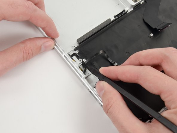
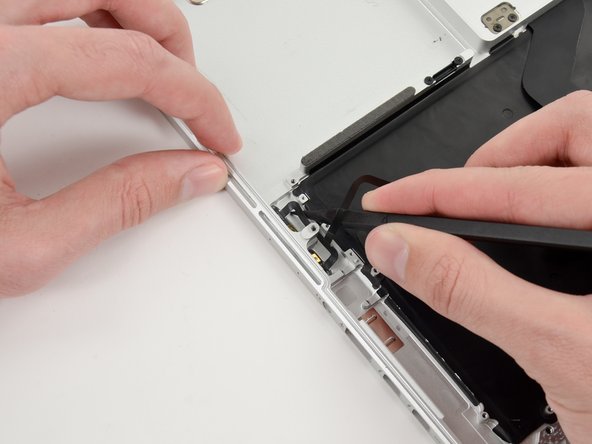
Wedge the tip of a spudger underneath the microphone assembly cable.
-
Run the spudger up along the bottom of the microphone assembly cable to separate it from the upper case.
-
-
이 단계는 번역되지 않았습니다. 번역을 도와주십시오
-
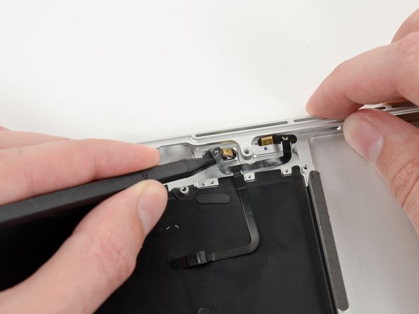
Gently wedge the tip of a spudger underneath the second microphone and push inwards to loosen the adhesive.
-


다른 7명이 해당 안내서를 완성하였습니다.

