이 버전에는 잘못된 편집 사항이 있을 수 있습니다. 최신 확인된 스냅샷으로 전환하십시오.
필요한 것
-
-
하단 케이스를 상단 케이스에 고정하는 다음 나사 열 개를 풀어주세요:
-
2.3mm P5 Pentalobe/펜타로브/별나사 두 개
-
3.0mm P5 Pentalobe/펜타로브/별나사 여덟 개
-
-
이 단계는 번역되지 않았습니다. 번역을 도와주십시오
-
Use the flat end of a spudger to peel the four foam stickers off of the heat sink screws.
-
-
이 단계는 번역되지 않았습니다. 번역을 도와주십시오
-
Remove the following screws securing the heat sink to the logic board:
-
One 2.7 mm T5 screw (silver)
-
Four T5 screws (black)
-
-
이 단계는 번역되지 않았습니다. 번역을 도와주십시오
-
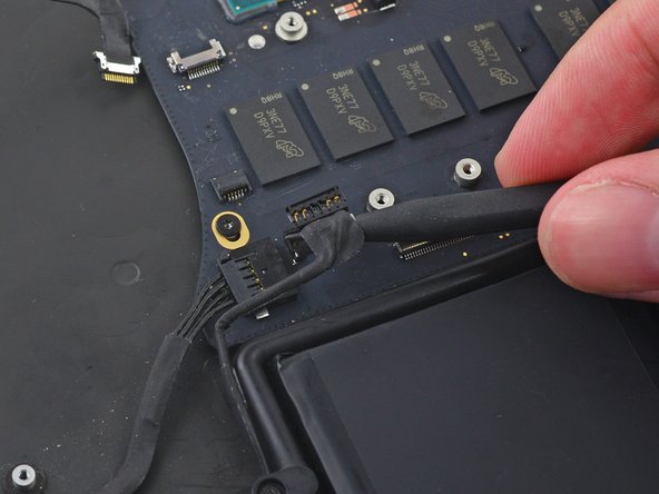
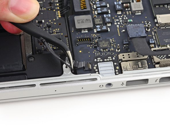
Use the tip of a spudger to push on either side of the the iSight camera cable connector to walk it out of its socket on the logic board.
-
-
이 단계는 번역되지 않았습니다. 번역을 도와주십시오
-
Peel the iSight camera cable off the fan housing to fold it out of the way.
-
-
이 단계는 번역되지 않았습니다. 번역을 도와주십시오
-
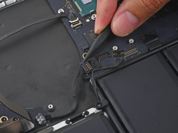
Use the tip of a spudger to flip the tab on the fan's ZIF connector.
-
Carefully pull the fan cable straight out of its socket.
-
-
이 단계는 번역되지 않았습니다. 번역을 도와주십시오
-
Remove the following screws securing the fan to the upper case:
-
One 5.0 mm T5 Torx screw
-
Two 3.6 mm T5 Torx screws
-
-
-
이 단계는 번역되지 않았습니다. 번역을 도와주십시오
-
Lift the end of the fan closest to the display hinge and remove the fan from the upper case.
-
-
이 단계는 번역되지 않았습니다. 번역을 도와주십시오
-
Remove the two 2.1 mm T5 Torx screws securing the I/O board cable bracket to the logic board.
-
Remove the I/O board cable bracket.
-
-
이 단계는 번역되지 않았습니다. 번역을 도와주십시오
-
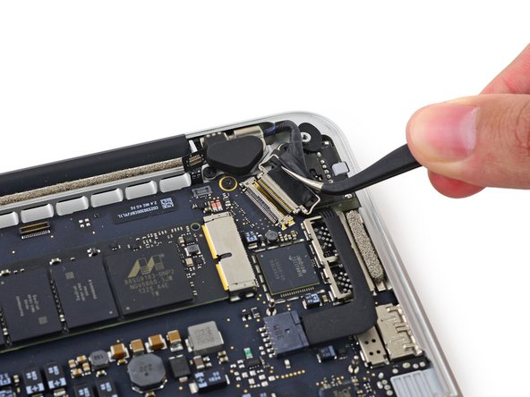
Use the flat end of a spudger to pop the I/O board connector straight up off its socket on the logic board.
-
-
이 단계는 번역되지 않았습니다. 번역을 도와주십시오
-
Lift the logic board end of the I/O board cable straight up to bend it out of the way.
-
-
이 단계는 번역되지 않았습니다. 번역을 도와주십시오
-
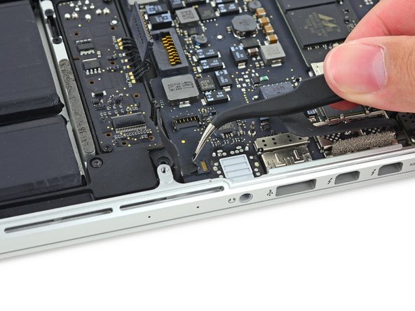
Use the tip of a spudger to lift the right speaker connector straight up out of its socket on the logic board.
-
-
이 단계는 번역되지 않았습니다. 번역을 도와주십시오
-
With the tip of a spudger, push on either side of the I/O board connector to walk it out of its socket on the logic board.
-
-
이 단계는 번역되지 않았습니다. 번역을 도와주십시오
-
Use the flat end of a spudger to disconnect the keyboard backlight cable and bend it up out of the way of the logic board.
-
-
이 단계는 번역되지 않았습니다. 번역을 도와주십시오
-
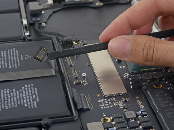
Grab the black plastic tab to flip the display cable connector open and pull it straight out of its socket on the logic board.
-
-
이 단계는 번역되지 않았습니다. 번역을 도와주십시오
-
Carefully pull the DC-In board connector straight out of its socket on the logic board.
-
-
이 단계는 번역되지 않았습니다. 번역을 도와주십시오
-
Wedge the flat end of a spudger under the left speaker cable near the connector and lift it straight up out of its socket and fold it out of the way.
-
-
이 단계는 번역되지 않았습니다. 번역을 도와주십시오
-
Use the tip of a spudger to flip the retaining tab on the microphone cable ZIF connector.
-
Pull the microphone cable out of its socket on the logic board.
-
-
이 단계는 번역되지 않았습니다. 번역을 도와주십시오
-
Use the tip of a spudger to flip the retaining tab on the ZIF connector.
-
-
이 단계는 번역되지 않았습니다. 번역을 도와주십시오
-
Pull the keyboard cable straight out of its ZIF socket on the logic board.
-
-
이 단계는 번역되지 않았습니다. 번역을 도와주십시오
-
Use the flat end of a spudger to pop the trackpad connector straight up off its socket on the logic board.
-
Fold the cable out back over the battery to clear the way for the logic board.
-
-
이 단계는 번역되지 않았습니다. 번역을 도와주십시오
-
Remove the five 3.5 mm T5 Torx screws securing the logic board to the upper case.
-
-
이 단계는 번역되지 않았습니다. 번역을 도와주십시오
-
Lift the processor end of the logic board up slightly and pull it toward the fan recess to free the ports from the edge of the upper case.
-
Remove the logic board.
-
-
이 단계는 번역되지 않았습니다. 번역을 도와주십시오
-
Remove the following screws securing the left speaker to the upper case:
-
One 5.7 mm T5 Torx screw
-
One 6.5 mm T5 Torx screw
-
One 3.8 mm T5 Torx screw
-
-
이 단계는 번역되지 않았습니다. 번역을 도와주십시오
-
Lift the corner of the left speaker up and slide it toward the battery to remove it from the upper case.
-
-
이 단계는 번역되지 않았습니다. 번역을 도와주십시오
-
Remove the single 3.7 mm T5 Torx screw securing the case-edge of the battery contact board.
-
-
이 단계는 번역되지 않았습니다. 번역을 도와주십시오
-
Insert the tip of a spudger under the battery-side portion of the rubber microphone cable cover to detach the adhesive there.
-
-
이 단계는 번역되지 않았습니다. 번역을 도와주십시오
-
Use the flat end of a spudger to wedge the battery contact board up slightly to allow room to extract the dual microphone assembly.
-
-
이 단계는 번역되지 않았습니다. 번역을 도와주십시오
-
이 단계는 번역되지 않았습니다. 번역을 도와주십시오
-
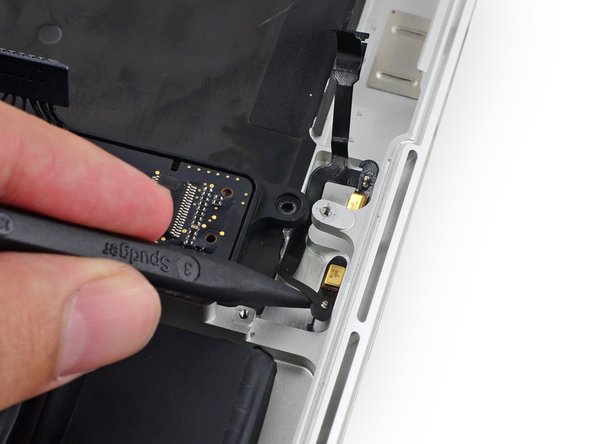
Insert the tip of a spudger underneath the connector end of the microphone ribbon cable and slide it toward the screw post to free that half from the upper case.
-
-
이 단계는 번역되지 않았습니다. 번역을 도와주십시오
-
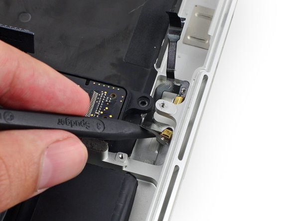
Insert the tip of a spudger under the battery-side portion of the microphone ribbon cable and slide it toward the screw post to free it from the upper case.
-
-
이 단계는 번역되지 않았습니다. 번역을 도와주십시오
-
Pull the dual microphone cable assembly up and toward the logic board recess to remove it from the upper case.
-


다른 10명이 해당 안내서를 완성하였습니다.

댓글 6개
Simply DISABLING the microphones can be done in 3 steps: #1, #2, #25, #26. No need to yank the logic board/fan and all that.
Many thanks for preparing / making this brilliant guide available. The mic in my Macbookpro failed for some reason and, using this guide I replaced it with a refurbished spare and saved myself $$. Every single step has been captured with specific additional detail / imagery where needed. It’s scary working with the tiny connectors but this guide gives you confidence it can be done / you can do it.
Nick Cassidy,
Where did you find a replacement? I have looked EVERYWHERE and can not find one.
Thanks!
This is the usual valuable guide to disassembly. However Steps 8-14 are NOT necessary and create added complication and potential for problems on reassembly. The motherboard can be safely removed with the fan and heatsink attached (make sure to leave the top right 3.6mm fan screw that secures to the motherboard – marked orange in Step 14 – in place). Obviously be careful not to place stress on the fan while it is only held on the one screw but otherwise there is no problem lifting and sliding the board at Step 31. I was able to get at the microphone easily after that and refitting the board was easily done too (making sure cables are not trapped underneath).
I'm slightly at a loss as to why removing the heat sink is deemed necessary unless this guide is based on another where that step is required.