이 버전에는 잘못된 편집 사항이 있을 수 있습니다. 최신 확인된 스냅샷으로 전환하십시오.
필요한 것
-
-
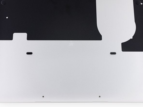
하단 케이스를 상단 케이스에 고정하는 다음 나사 열 개를 풀어주세요:
-
2.3mm P5 Pentalobe/펜타로브/별나사 두 개
-
3.0mm P5 Pentalobe/펜타로브/별나사 여덟 개
-
-
-
이 단계는 번역되지 않았습니다. 번역을 도와주십시오
-
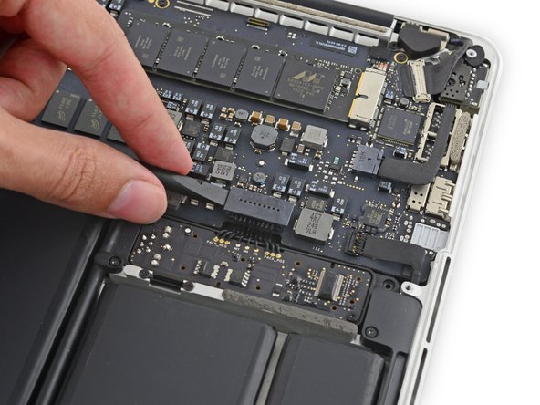
Use the flat end of a spudger to peel the four foam stickers off of the heat sink screws.
-
-
이 단계는 번역되지 않았습니다. 번역을 도와주십시오
-
Remove the following screws securing the heat sink to the logic board:
-
One 2.7 mm T5 screw (silver)
-
Four T5 screws (black)
-
다른 56명이 해당 안내서를 완성하였습니다.
댓글 5개
what part should i purchae to get the rubber fan bumper?
Bonjour !
Merci pour ce tutoriel de qualité ! Pour la pâte thermique, j’ai opté pour la Grizzly Kryonaut… Un peu overkill pour un MBP 13” de 2015, mais cela devrait contribuer à sa longévité !
Une remarque cependant : sur mon modèle, la vis en ROUGE de l’ETAPE 9 n’était pas une Torx T5, mais une Y00 ! Cela ne m’a pas posé de problème car j’avais le kit complet de tournevis, mais cela l’aurait été si je n’avais acheté qu’un P5 et un T5 ! Faites attention !
Bonne continuation !
PS: si certains doutent de leurs capacités à réaliser cette opération, sachez que je suis grand débutant en informatique et que je n’ai eu AUCUN problème. La partie la plus ardue étant le retrait du connecteur de la batterie !
Used this guide to pop the heat sink and scrape off the old thermal paste. Cleaned and re-applied with new paste, hopefully leading to better thermal performance. One thing I noticed is that the heatsink doesn’t cover the second module (presumed to be the integrated GPU) next to the CPU? Perhaps this is why thermal performance is so abysmal on these little guys.
In my MacBook Pro, the screw in step 9 that is farthest away from the CPU is a Philips screw, rather than T5 Torx.
I bought my MacBook Pro in 2016, over a year after it came out, so this might be different depending on when yours was manufactured.


