이 버전에는 잘못된 편집 사항이 있을 수 있습니다. 최신 확인된 스냅샷으로 전환하십시오.
필요한 것
-
-
하단 케이스를 상단 케이스에 고정하는 다음 나사 열 개를 풀어주세요:
-
2.3mm P5 Pentalobe/펜타로브/별나사 두 개
-
3.0mm P5 Pentalobe/펜타로브/별나사 여덟 개
-
-
이 단계는 번역되지 않았습니다. 번역을 도와주십시오
-
Use the flat end of a spudger to peel the four foam stickers off of the heat sink screws.
-
-
이 단계는 번역되지 않았습니다. 번역을 도와주십시오
-
Remove the following screws securing the heat sink to the logic board:
-
Four 2.6 mm T5 screws
-
One 2.4 mm Phillips #000 screw
-
-
이 단계는 번역되지 않았습니다. 번역을 도와주십시오
-
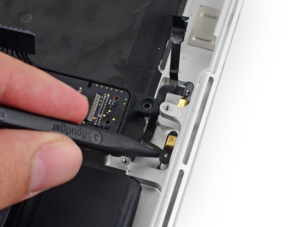
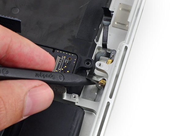
Use the tip of a spudger to push on either side of the the iSight camera cable connector to walk it out of its socket on the logic board.
-
-
이 단계는 번역되지 않았습니다. 번역을 도와주십시오
-
Peel the iSight camera cable off the fan housing to fold it out of the way.
-
-
이 단계는 번역되지 않았습니다. 번역을 도와주십시오
-
Use the tip of a spudger to flip the tab on the fan's ZIF connector.
-
Carefully pull the fan cable straight out of its socket.
-
-
이 단계는 번역되지 않았습니다. 번역을 도와주십시오
-
Remove the following screws securing the fan to the upper case:
-
One 5.0 mm T5 Torx screw
-
Two 3.6 mm T5 Torx screws
-
-
-
이 단계는 번역되지 않았습니다. 번역을 도와주십시오
-
Lift the end of the fan closest to the display hinge and remove the fan from the upper case.
-
-
이 단계는 번역되지 않았습니다. 번역을 도와주십시오
-
Remove the two 2.1 mm T5 Torx screws securing the I/O board cable bracket to the logic board.
-
Remove the I/O board cable bracket.
-
-
이 단계는 번역되지 않았습니다. 번역을 도와주십시오
-
Use the flat end of a spudger to pop the I/O board connector straight up off its socket on the logic board.
-
-
이 단계는 번역되지 않았습니다. 번역을 도와주십시오
-
Lift the logic board end of the I/O board cable straight up to bend it out of the way.
-
-
이 단계는 번역되지 않았습니다. 번역을 도와주십시오
-
Use the tip of a spudger to lift the right speaker connector straight up out of its socket on the logic board.
-
-
이 단계는 번역되지 않았습니다. 번역을 도와주십시오
-
With the tip of a spudger, push on either side of the I/O board connector to walk it out of its socket on the logic board.
-
-
이 단계는 번역되지 않았습니다. 번역을 도와주십시오
-
Use the flat end of a spudger to disconnect the keyboard backlight cable and bend it up out of the way of the logic board.
-
-
이 단계는 번역되지 않았습니다. 번역을 도와주십시오
-
Grab the black plastic tab to flip the display cable connector open and pull it straight out of its socket on the logic board.
-
-
이 단계는 번역되지 않았습니다. 번역을 도와주십시오
-
Carefully pull the DC-In board connector straight out of its socket on the logic board.
-
-
이 단계는 번역되지 않았습니다. 번역을 도와주십시오
-
Wedge the flat end of a spudger under the left speaker cable near the connector and lift it straight up out of its socket and fold it out of the way.
-
-
이 단계는 번역되지 않았습니다. 번역을 도와주십시오
-
Use the tip of a spudger to flip the retaining tab on the microphone cable ZIF connector.
-
Pull the microphone cable out of its socket on the logic board.
-
-
이 단계는 번역되지 않았습니다. 번역을 도와주십시오
-
Use the tip of a spudger to flip the retaining tab on the ZIF connector.
-
-
이 단계는 번역되지 않았습니다. 번역을 도와주십시오
-
Pull the keyboard cable straight out of its ZIF socket on the logic board.
-
-
이 단계는 번역되지 않았습니다. 번역을 도와주십시오
-
Use the tip of a spudger to flip the retaining tab on the ZIF connector.
-
-
이 단계는 번역되지 않았습니다. 번역을 도와주십시오
-
Pull the trackpad ribbon cable straight out of its socket on the logic board.
-
-
이 단계는 번역되지 않았습니다. 번역을 도와주십시오
-
Remove the five 3.5 mm T5 Torx screws securing the logic board to the upper case.
-
-
이 단계는 번역되지 않았습니다. 번역을 도와주십시오
-
Lift the processor end of the logic board up slightly and pull it toward the fan recess to free the ports from the edge of the upper case.
-
Remove the logic board.
-
-
이 단계는 번역되지 않았습니다. 번역을 도와주십시오
-
Remove the following screws securing the left speaker to the upper case:
-
One 5.7 mm T5 Torx screw
-
One 6.5 mm T5 Torx screw
-
One 3.8 mm T5 Torx screw
-
-
이 단계는 번역되지 않았습니다. 번역을 도와주십시오
-
Lift the corner of the left speaker up and slide it toward the battery to remove it from the upper case.
-
-
이 단계는 번역되지 않았습니다. 번역을 도와주십시오
-
Remove the single 3.7 mm T5 Torx screw securing the case-edge of the battery contact board.
-
-
이 단계는 번역되지 않았습니다. 번역을 도와주십시오
-
Insert the tip of a spudger under the battery-side portion of the rubber microphone cable cover to detach the adhesive there.
-
-
이 단계는 번역되지 않았습니다. 번역을 도와주십시오
-
Use the flat end of a spudger to wedge the battery contact board up slightly to allow room to extract the dual microphone assembly.
-
-
이 단계는 번역되지 않았습니다. 번역을 도와주십시오
-
Insert the tip of a spudger underneath the connector end of the microphone ribbon cable and slide it toward the screw post to free that half from the upper case.
-
-
이 단계는 번역되지 않았습니다. 번역을 도와주십시오
-
Insert the tip of a spudger under the battery-side portion of the microphone ribbon cable and slide it toward the screw post to free it from the upper case.
-
-
이 단계는 번역되지 않았습니다. 번역을 도와주십시오
-
Pull the dual microphone cable assembly up and toward the logic board recess to remove it from the upper case.
-


다른 2명이 해당 안내서를 완성하였습니다.

