이 버전에는 잘못된 편집 사항이 있을 수 있습니다. 최신 확인된 스냅샷으로 전환하십시오.
필요한 것
-
-
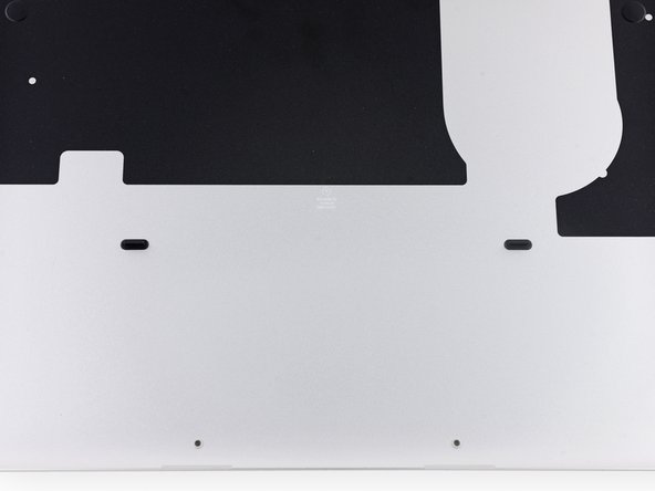
하단 케이스를 상단 케이스에 고정하는 다음 나사 열 개를 풀어주세요:
-
2.3mm P5 Pentalobe/펜타로브/별나사 두 개
-
3.0mm P5 Pentalobe/펜타로브/별나사 여덟 개
-
-
이 단계는 번역되지 않았습니다. 번역을 도와주십시오
-
Use the flat end of a spudger to peel the four foam stickers off of the heat sink screws.
-
-
이 단계는 번역되지 않았습니다. 번역을 도와주십시오
-
Remove the following screws securing the heat sink to the logic board:
-
Four 2.6 mm T5 screws
-
One 2.4 mm Phillips #000 screw
-
-
이 단계는 번역되지 않았습니다. 번역을 도와주십시오
-
Use the tip of a spudger to push on either side of the the iSight camera cable connector to walk it out of its socket on the logic board.
-
-
이 단계는 번역되지 않았습니다. 번역을 도와주십시오
-
Peel the iSight camera cable off the fan housing to fold it out of the way.
-
-
-
이 단계는 번역되지 않았습니다. 번역을 도와주십시오
-
Use the tip of a spudger to flip the tab on the fan's ZIF connector.
-
Carefully pull the fan cable straight out of its socket.
-
-
이 단계는 번역되지 않았습니다. 번역을 도와주십시오
-
Remove the following screws securing the fan to the upper case:
-
One 5.0 mm T5 Torx screw
-
Two 3.6 mm T5 Torx screws
-
-
이 단계는 번역되지 않았습니다. 번역을 도와주십시오
-
Lift the end of the fan closest to the display hinge and remove the fan from the upper case.
-
-
이 단계는 번역되지 않았습니다. 번역을 도와주십시오
-
Remove the two 2.1 mm T5 Torx screws securing the I/O board cable bracket to the logic board.
-
Remove the I/O board cable bracket.
-
-
이 단계는 번역되지 않았습니다. 번역을 도와주십시오
-
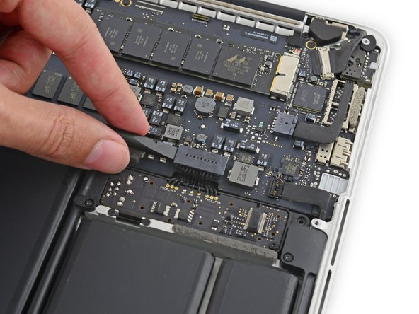
Use the flat end of a spudger to pop the I/O board connector straight up off its socket on the logic board.
-
-
이 단계는 번역되지 않았습니다. 번역을 도와주십시오
-
Lift the logic board end of the I/O board cable straight up to bend it out of the way.
-
-
이 단계는 번역되지 않았습니다. 번역을 도와주십시오
-
Use the tip of a spudger to lift the right speaker connector straight up out of its socket on the logic board.
-
-
이 단계는 번역되지 않았습니다. 번역을 도와주십시오
-
With the tip of a spudger, push on either side of the I/O board connector to walk it out of its socket on the logic board.
-
-
이 단계는 번역되지 않았습니다. 번역을 도와주십시오
-
Use the flat end of a spudger to disconnect the keyboard backlight cable and bend it up out of the way of the logic board.
-
-
이 단계는 번역되지 않았습니다. 번역을 도와주십시오
-
Grab the black plastic tab to flip the display cable connector open and pull it straight out of its socket on the logic board.
-
-
이 단계는 번역되지 않았습니다. 번역을 도와주십시오
-
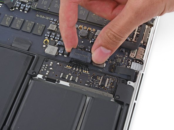
Carefully pull the DC-In board connector straight out of its socket on the logic board.
-
-
이 단계는 번역되지 않았습니다. 번역을 도와주십시오
-
Wedge the flat end of a spudger under the left speaker cable near the connector and lift it straight up out of its socket and fold it out of the way.
-
-
이 단계는 번역되지 않았습니다. 번역을 도와주십시오
-
Use the tip of a spudger to flip the retaining tab on the microphone cable ZIF connector.
-
Pull the microphone cable out of its socket on the logic board.
-
-
이 단계는 번역되지 않았습니다. 번역을 도와주십시오
-
Use the tip of a spudger to flip the retaining tab on the ZIF connector.
-
-
이 단계는 번역되지 않았습니다. 번역을 도와주십시오
-
Pull the keyboard cable straight out of its ZIF socket on the logic board.
-
-
이 단계는 번역되지 않았습니다. 번역을 도와주십시오
-
Use the tip of a spudger to flip the retaining tab on the ZIF connector.
-
-
이 단계는 번역되지 않았습니다. 번역을 도와주십시오
-
Pull the trackpad ribbon cable straight out of its socket on the logic board.
-
-
이 단계는 번역되지 않았습니다. 번역을 도와주십시오
-
Remove the five 3.5 mm T5 Torx screws securing the logic board to the upper case.
-
-
이 단계는 번역되지 않았습니다. 번역을 도와주십시오
-
Lift the processor end of the logic board up slightly and pull it toward the fan recess to free the ports from the edge of the upper case.
-
Remove the logic board.
-
-
이 단계는 번역되지 않았습니다. 번역을 도와주십시오
-
Remove the single 2.9 mm T5 Torx screw securing the SSD to the logic board.
-
-
이 단계는 번역되지 않았습니다. 번역을 도와주십시오
-
Lift the free end of the SSD up slightly and pull it straight out of its socket on the logic board.
-
다른 75명이 해당 안내서를 완성하였습니다.
댓글 12개
This guide helped me repair my MacBook Pro with no prior knowledge of working on computers. I purchased a new logic board after mine broke from eBay, from a seller named L2 Computer Inc. and followed this guide using the iFixit pro tech tool kit and their thermal compound application set to reinstall the heat sink, and my computer turned on right away. Everything was so easy using this guide. The pictures are so good at showing how to do the steps, and the tool kit had really nice tools which made the whole process very simple. I am so thankful that you all help people fix their computers. It could not have been easier with this guide. It’s very well-written.
Great guide. Had issues with my Late 2013 MBP and narrowed it down to the logic board. I replaced it with a Mid-2014 MBP logic board as they are interchangeable thanks to this detailed guide. Laptop now fixed and upgraded!
I can’t say enough about how well done this guide is for replacing a late 2013 MacBook logic board. The step by step with pictures were professional and spot on. I had a 4GB, i5 that had got to the point where I had to keep using a memory app to free up memory every couple minutes. Not being able to upgrade memory I was left with little options other than to buy a new one. After finding this site, I got a new logic board with i7 and 16GB of memory, I was able to turn my crippling MacBook back into a robust laptop I can once again enjoy using hopefully for at least a few more years. Bought the tools on here to complete the replacement and everything went without a hitch.
So a BIG thank you, thank you, thank you.. Keep up the great work on this site.. I know I’ll be back to check in on what’s available and when I have something else that needs to be fixed/upgraded vs buying new. :)
Boston222
@boston222 I am in a similar situation where my 4GB memory is killing me. Would you be able to let me know where you got your i7 with 16GB of memory? I have been looking but I cannot find an i7 .. all I find is i5 with 16GB of memory .. I would appreciate if you could provide a website or model number of the item you ordered so I could get the same one.
Thanks in advance!
Hari -


