이 버전에는 잘못된 편집 사항이 있을 수 있습니다. 최신 확인된 스냅샷으로 전환하십시오.
필요한 것
-
이 단계는 번역되지 않았습니다. 번역을 도와주십시오
-
Turn the keyboard locking screw so that it is parallel to the space bar.
-
Pull the keyboard release tabs toward you and lift up on the keyboard until it pops free.
-
Lift the keyboard out by pulling it up and away from you. Rest the keyboard, face down, on top of the track pad.
-
-
이 단계는 번역되지 않았습니다. 번역을 도와주십시오
-
Pull the keyboard ribbon straight up from the logic board. Place the keyboard aside.
-
-
이 단계는 번역되지 않았습니다. 번역을 도와주십시오
-
Remove the two silver Phillips #1 screws that attach the heat shield to the internal metal framework.
-
Lift the heat shield up and pull it toward you.
-
-
이 단계는 번역되지 않았습니다. 번역을 도와주십시오
-
Firmly grasp the plastic tab attached to the Airport card and pull up and then to the right.
-
-
이 단계는 번역되지 않았습니다. 번역을 도와주십시오
-
Pull the battery cable directly up from the logic board.
-
Remove the battery from its holder by pulling up and to the left.
-
-
이 단계는 번역되지 않았습니다. 번역을 도와주십시오
-
Remove the long silver Phillips #1 screw from the heat sink.
-
Remove the two T8 Torx screws that attach the heat sink to the processor.
-
-
이 단계는 번역되지 않았습니다. 번역을 도와주십시오
-
Grasp the plastic tab on the processor's right side and pull it directly up.
-
-
이 단계는 번역되지 않았습니다. 번역을 도와주십시오
-
Remove the black Torx screw from the right side of the modem.
-
Remove the small black plastic rectangle with four holes.
-
-
이 단계는 번역되지 않았습니다. 번역을 도와주십시오
-
Use the tips of your fingers, a spudger, or a flat non-metal tool to get under the modem's edge and pry it up from its socket.
-
-
이 단계는 번역되지 않았습니다. 번역을 도와주십시오
-
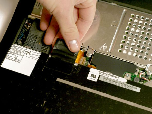
Grasp the orange cable at the left end of the hard drive and disconnect it from the logic board.
-
-
-
이 단계는 번역되지 않았습니다. 번역을 도와주십시오
-
Grasp the plastic tab and pull the hard drive up and to the left, making sure that the metal bracket doesn't catch on the black plastic casing.
-
-
이 단계는 번역되지 않았습니다. 번역을 도와주십시오
-
Push the display back so that it lies flat.
-
Slip your index finger or a nylon tool under the clutch cover near the power button and pull gently upward until you feel it come free.
-
Repeat the previous step on the left side.
-
-
이 단계는 번역되지 않았습니다. 번역을 도와주십시오
-
Grasp the orange display data cable and disconnect it from the logic board.
-
-
이 단계는 번역되지 않았습니다. 번역을 도와주십시오
-
Remove the single black Torx screw that fastens the display cable to the plastic casing.
-
Grasp the thin display inverter board at its left end; lift up and rotate toward yourself.
-
-
이 단계는 번역되지 않았습니다. 번역을 도와주십시오
-
Disconnect the inverter plug, pulling directly up from the logic board.
-
-
이 단계는 번역되지 않았습니다. 번역을 도와주십시오
-
Turn the laptop around so that its back faces you.
-
Open the port door located at the back of the laptop.
-
Remove the four black Torx screws.
-
-
이 단계는 번역되지 않았습니다. 번역을 도와주십시오
-
Returning to the front, pull the black Airport antenna up from its recessed housing.
-
-
이 단계는 번역되지 않았습니다. 번역을 도와주십시오
-
Hold the display on both sides and pull directly up until its hinges are free of their mounts.
-
-
이 단계는 번역되지 않았습니다. 번역을 도와주십시오
-
Disconnect the wide orange cable that connects the airport card slot to the logic board.
-
-
이 단계는 번역되지 않았습니다. 번역을 도와주십시오
-
Remove the three long silver and one short black Torx screws from the beige plastic casing.
-
-
이 단계는 번역되지 않았습니다. 번역을 도와주십시오
-
Slide the thin plastic shield away from you, out from under the black casing.
-
Disconnect the newly revealed thin orange ribbon from the logic board.
-
Remove the two long silver Torx screws.
-
-
이 단계는 번역되지 않았습니다. 번역을 도와주십시오
-
Turn the laptop over.
-
Remove the five short Torx screws from the bottom casing.
-
Remove the two long Torx screws in the front left and front right corners; make sure to put these back in the proper place when reassembling.
-
-
이 단계는 번역되지 않았습니다. 번역을 도와주십시오
-
Turn the laptop back over.
-
Remove three short black Torx screws from the metal frame.
-
Remove the small Torx screw to the far left that fastens the logic board to the casing.
-
-
이 단계는 번역되지 않았습니다. 번역을 도와주십시오
-
Grasp the upper plastic casing where it locks into the internal frame and pull back. When the plastic tab has cleared the slot that the casing locks into, pull up enough to keep it from locking back into place.
-
-
이 단계는 번역되지 않았습니다. 번역을 도와주십시오
-
The PC card eject button on the laptop's left side prevents the upper casing from lifting up. In order to bypass the button, push it in far enough so that you can pull the upper casing's left side out and up beyond the button.
-
-
이 단계는 번역되지 않았습니다. 번역을 도와주십시오
-
Lift the left side of the case partly up so that you can access and disconnect the audio in/out cables from the sound card in the upper right of the case.
-
Remove the upper casing. Note that there are two tabs on the laptop's front that often cause the upper case to stick.
-
-
이 단계는 번역되지 않았습니다. 번역을 도와주십시오
-
Remove the two long silver Torx screws from the power card in the center of the laptop
-
-
이 단계는 번역되지 않았습니다. 번역을 도와주십시오
-
Gently clasp the left side of the metal shield between your thumb and forefinger and carefully pull up and toward the front of the laptop.
-
-
이 단계는 번역되지 않았습니다. 번역을 도와주십시오
-
Remove the single short black Torx screw anchoring the metal framework to the lower casing.
-
Use needle-nose pliers or a five millimeter nut driver to remove the small metal nut from the bolt.
-
-
이 단계는 번역되지 않았습니다. 번역을 도와주십시오
-
Turn the laptop so that its back is facing you.
-
Lift up on the left side of the metal framework and remove the single black Torx screw.
-
-
이 단계는 번역되지 않았습니다. 번역을 도와주십시오
-
Grasp the EMI Filter by its black end and rotate it toward the front of the laptop. Pull the filter up and beyond the screw bracket.
-
Remove the metal framework.
-
-
이 단계는 번역되지 않았습니다. 번역을 도와주십시오
-
Lift the sound card out by pulling up on both the right and left sides.
-
-
이 단계는 번역되지 않았습니다. 번역을 도와주십시오
-
Turn the laptop around so that the front faces you.
-
Move the metal yoke to the left.
-


다른 7명이 해당 안내서를 완성하였습니다.
첨부 문서

댓글 4개
It should be noted (at least in my case) that it takes a considerable amount of pressure to snap the processor connector back into place on the logic board when reinstalling it step 12. I learned this the hard way, requiring another dis-assembly. I'd hate to say that you really have to shove on it, but at least put some strong pressure on the processor directly above the connector point, which is hidden under the card. It helped me to remove the memory module so that I could place my two fingers there and push with a little rocking motion.
To follow up on my last note regarding the processor card connector: On the next Pismo I worked on, I added an almost microscopic amount of silicone dielectric compound to the outside of the 6 tiny beveled plastic pin edges on the connector side that is mounted to the logic board. I applied the dielectric compound with a toothpick. This small amount of lubrication made it much easier to snap the connector down to the logic board.