주요 콘텐츠로 건너뛰기

Protocol TerraCopter EVO Controller Motherboard Replacement

필요한 것

  1. Protocol TerraCopter EVO Controller Motherboard Replacement, Controller's battery: 1 단계, 이미지 1/2 Protocol TerraCopter EVO Controller Motherboard Replacement, Controller's battery: 1 단계, 이미지 2/2
    • Using a Phillips #0 screwdriver, remove the screw connecting the battery cover to the controller.

    • Remove the battery cover from the controller.

  2. Protocol TerraCopter EVO Controller Motherboard Replacement: 2 단계, 이미지 1/1
    • Remove all of four of the AA batteries from the controller.

  3. 주의: 3-4 단계들은 진행 중으로 표시된 안내서에서 제공되었습니다.

    Protocol TerraCopter EVO Controller Motherboard Replacement, Protocol TerraCopter EVO Controller Opening: 3 단계, 이미지 1/1
    • Note: the four Phillips screws on the rear panel are a millimeter longer than the two screws near the antenna and the two screws on the handle.

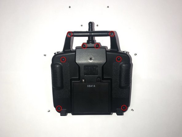
    • Orientate the controller to where the battery compartment is facing upwards.

    • Remove the four 5mm and four 4mm Phillips #1 screws from the case.

  4. Protocol TerraCopter EVO Controller Motherboard Replacement: 4 단계, 이미지 1/1
    • Since the battery wires are still attached, carefully move the rear panel down to expose the motherboard.

  5. Protocol TerraCopter EVO Controller Motherboard Replacement, Controller Motherboard: 5 단계, 이미지 1/1
    • Remove the eight 5mm Phillips #1 screws from the motherboard.

  6. Protocol TerraCopter EVO Controller Motherboard Replacement: 6 단계, 이미지 1/1
    • Locate the set of four green wires and one black wire attached to the motherboard.

    • Remove the male, white connector by pressing up on the two tabs on the female connector. Then, pull the connector away from the female connector on the motherboard

  7. Protocol TerraCopter EVO Controller Motherboard Replacement: 7 단계, 이미지 1/1
    • Locate the single pin holding the negative and positive wires to the motherboard. Each lead should have one pin holding each wire to the green side of the motherboard.

    • Using a soldering iron, melt the existing solder point for the red lead (positive line).

    • Using a soldering iron, melt the existing solder point for the black lead (negative line).

    • Pull the red and black leads through their respective holes, out of the motherboard.

    • Check out our How to Solder and Desolder Connections guide if you are unfamiliar with soldering practices.

결론

To reassemble your device, follow these instructions in reverse order.

다른 한 분이 해당 안내서를 완성하였습니다.

Jonathan Earls

회원 가입일: 10/03/19

127 평판

안내서 1개 작성함

댓글 0개

댓글 쓰기

조회 통계:

24 시간 전: 0

7일 전: 0

30일 전: 5

전체 시간: 96