이 버전에는 잘못된 편집 사항이 있을 수 있습니다. 최신 확인된 스냅샷으로 전환하십시오.
필요한 것
-
이 단계는 번역되지 않았습니다. 번역을 도와주십시오
-
Remove the following eight screws securing the lower case:
-
Two 1.8 mm P5 Pentalobe screws
-
Four 2.9 mm P5 Pentalobe screws
-
Two 6.1 mm P5 Pentalobe screws
-
-
이 단계는 번역되지 않았습니다. 번역을 도와주십시오
-
Wedge your fingers between the upper case and the lower case, starting from the rear of the MacBook between the hinges.
-
Keeping a firm grip, lift steadily until the lower case separates slightly from the upper case.
-
-
이 단계는 번역되지 않았습니다. 번역을 도와주십시오
-
While holding the lower case in place, carefully flip the MacBook over so the Apple logo faces up.
-
-
이 단계는 번역되지 않았습니다. 번역을 도와주십시오
-
Lift the upper case and display together from the front edge and raise it to about a 45˚ angle.
-
-
이 단계는 번역되지 않았습니다. 번역을 도와주십시오
-
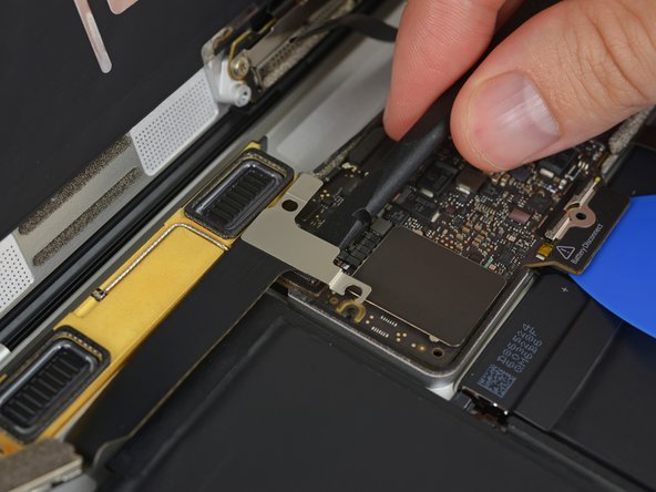
Use the flat end of a spudger to press and hold the small gold 'battery disconnect' button.
-
If the power LED is lit up, continue holding the button until the LED goes dark, and then release. This may take up to 10 seconds.
-
If the LED does not light, release the button after 5-10 seconds. Press and hold it again for 5-10 seconds, and release. Finally, press and hold it a third time for 5-10 seconds, and release.
-
-
이 단계는 번역되지 않았습니다. 번역을 도와주십시오
-
Lifting from the front edge, open the lower case to an angle of about 45°.
-
-
이 단계는 번역되지 않았습니다. 번역을 도와주십시오
-
Use tweezers to peel back the tape covering the trackpad cable ZIF connector.
-
-
이 단계는 번역되지 않았습니다. 번역을 도와주십시오
-
Use a spudger to carefully flip up the retaining flap on the trackpad cable ZIF connector.
-
-
이 단계는 번역되지 않았습니다. 번역을 도와주십시오
-
Disconnect the trackpad ribbon cable from the trackpad by pulling it gently through its slot in the frame.
-
-
이 단계는 번역되지 않았습니다. 번역을 도와주십시오
-
Carefully turn the MacBook over, so that the lower case lays flat.
-
Raise the upper case/display assembly to about a 90° angle, and prop it up against something sturdy so you don't have to hold it.
-
Add a piece of tape near the track pad to secure the upper case and prevent accidental movement.
-
-
이 단계는 번역되지 않았습니다. 번역을 도와주십시오
-
Remove the single 2.9 mm T5 Torx screw securing the battery connector to the logic board.
-
-
이 단계는 번역되지 않았습니다. 번역을 도와주십시오
-
As an added precaution, you may physically disconnect the battery by inserting a battery isolation pick between the logic board and the battery connector.
-
-
이 단계는 번역되지 않았습니다. 번역을 도와주십시오
-
Remove the two screws securing the USB-C port cable bracket:
-
1.1 mm Tri-point Y00 screw
-
3.5 mm T5 Torx screw
-
-
이 단계는 번역되지 않았습니다. 번역을 도와주십시오
-
Use the flat end of a spudger to disconnect the USB-C port cable bracket by prying it straight up from the logic board.
-
-
이 단계는 번역되지 않았습니다. 번역을 도와주십시오
-
Use a spudger to flip open the retaining flap on the audio jack board cable ZIF connector.
-
-
이 단계는 번역되지 않았습니다. 번역을 도와주십시오
-
Disconnect the audio jack board ribbon cable by pulling it straight back out of the ZIF connector.
-
-
-
이 단계는 번역되지 않았습니다. 번역을 도와주십시오
-
Use tweezers to peel back the tape covering the display cable connector.
-
-
이 단계는 번역되지 않았습니다. 번역을 도와주십시오
-
If so, use the flat end of a spudger to hold down the retaining flap while peeling the tape away with the tweezers.
-
-
이 단계는 번역되지 않았습니다. 번역을 도와주십시오
-
Use the flat end of a spudger to flip open the retaining flap on the display cable connector.
-
Try to keep it clear of the tape, or it may re-adhere and make cable removal difficult.
-
-
이 단계는 번역되지 않았습니다. 번역을 도와주십시오
-
Carefully slide the flat end of a spudger underneath the display cable to separate the adhesive holding it to the lower case.
-
-
이 단계는 번역되지 않았습니다. 번역을 도와주십시오
-
Disconnect the display cable by gently pulling it straight out of its connector.
-
-
이 단계는 번역되지 않았습니다. 번역을 도와주십시오
-
Use tweezers to peel up the tape covering the two ZIF connectors—one for the right speaker cable, and one for the audio jack board cable.
-
-
이 단계는 번역되지 않았습니다. 번역을 도와주십시오
-
Use the point of a spudger to flip up both ZIF connector retaining flaps.
-
-
이 단계는 번역되지 않았습니다. 번역을 도와주십시오
-
Carefully pull straight back on the two pieces of tape you just peeled up to disconnect the two ribbon cables.
-
-
이 단계는 번역되지 않았습니다. 번역을 도와주십시오
-
Use the point of a spudger to peel up the foam pad covering the two antenna connectors.
-
-
이 단계는 번역되지 않았습니다. 번역을 도와주십시오
-
Insert one arm of your angled tweezers under the metal neck of the first antenna connector and pry up to disconnect it.
-
-
이 단계는 번역되지 않았습니다. 번역을 도와주십시오
-
Use a spudger to disconnect the left speaker cable connector by prying it straight up from the logic board.
-
-
이 단계는 번역되지 않았습니다. 번역을 도와주십시오
-
Use a spudger to flip up the retaining flap on the trackpad cable ZIF connector.
-
-
이 단계는 번역되지 않았습니다. 번역을 도와주십시오
-
Disconnect the trackpad cable from the logic board by gently pulling it straight out of its connector.
-
-
이 단계는 번역되지 않았습니다. 번역을 도와주십시오
-
Remove the single 3.5 mm T5 Torx screw securing the logic board to the lower case.
-
-
이 단계는 번역되지 않았습니다. 번역을 도와주십시오
-
Flip up the front edge of the logic board.
-
Lift and detach the EMI tape securing the logic board to the lower case.
-
-
이 단계는 번역되지 않았습니다. 번역을 도와주십시오
-
Lift the back edge of the lower case assembly and prop it up at an angle using a book or foam block.
-
-
이 단계는 번역되지 않았습니다. 번역을 도와주십시오
-
Wear eye protection when handling and applying the adhesive remover. (Eye protection is included in your kit.)
-
Do not wear contact lenses without eye protection.
-
Protective gloves are also included in your kit. If you are concerned about skin irritation, put your gloves on now.
-
-
이 단계는 번역되지 않았습니다. 번역을 도와주십시오
-
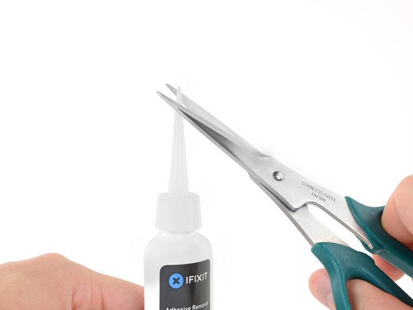
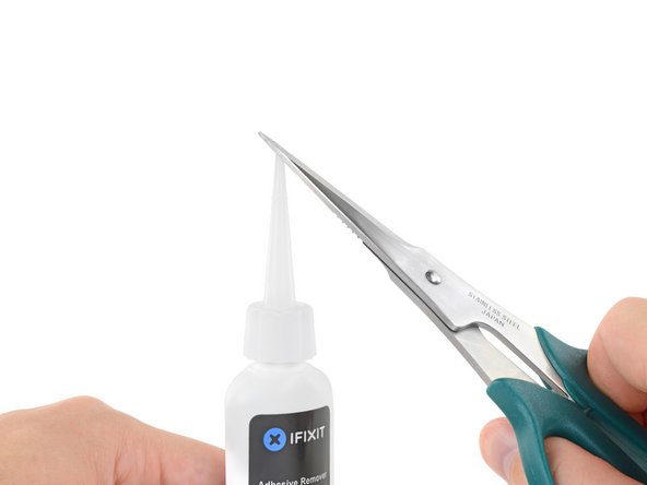
Pull off the black rubber stopper from your bottle of adhesive remover.
-
Use scissors to cut off the sealed tip of the applicator.
-
-
이 단계는 번역되지 않았습니다. 번역을 도와주십시오
-
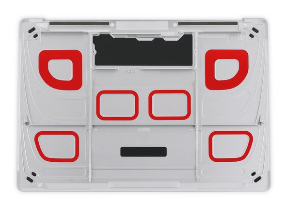
The adhesive securing the battery cells to the lower case is located in the areas marked in red.
-
-
이 단계는 번역되지 않았습니다. 번역을 도와주십시오
-
Apply a few drops of adhesive remover along the top edge of the front right battery cell.
-
Wait 2-3 minutes for the liquid adhesive remover to penetrate underneath the battery cell before you proceed to the next step.
-
-
이 단계는 번역되지 않았습니다. 번역을 도와주십시오
-
After 2-3 minutes, slide one corner of a plastic card underneath the battery cell.
-
Slide the card farther underneath the battery cell to separate it from the adhesive securing it to the case.
-
-
이 단계는 번역되지 않았습니다. 번역을 도와주십시오
-
Lift the battery cell from the right edge to fully separate it from the adhesive, but don't try to remove it.
-
Leave the plastic card underneath the battery cell to prevent it from re-adhering as you proceed to the next step.
-
-
이 단계는 번역되지 않았습니다. 번역을 도와주십시오
-
Repeat the previous three steps to separate the front left battery cell.
-
Leave the plastic card underneath the battery cell to prevent it from re-adhering as you proceed to the next step.
-
-
이 단계는 번역되지 않았습니다. 번역을 도와주십시오
-
Repeat the previous steps to separate the large battery cell on the left side of the MacBook.
-
-
이 단계는 번역되지 않았습니다. 번역을 도와주십시오
-
Repeat the previous steps to separate the large battery cell on the right side of the MacBook.
-
-
이 단계는 번역되지 않았습니다. 번역을 도와주십시오
-
Lay the lower case assembly down flat, and apply adhesive remover to the two middle battery cells—at each side, and along the front edge (opposite the logic board area).
-
-
이 단계는 번역되지 않았습니다. 번역을 도와주십시오
-
Apply some additional adhesive remover down the middle between the two battery cells.
-
Wait 2-3 minutes for the adhesive remover to penetrate before you proceed.
-
-
이 단계는 번역되지 않았습니다. 번역을 도와주십시오
-
Insert your plastic card under the front edge one of the battery cells and separate it carefully.
-
-
이 단계는 번역되지 않았습니다. 번역을 도와주십시오
-
Remove the battery by lifting it away from the speaker and logic board area.
-
Peel off larger pieces of adhesive using tweezers or gloved fingers.
-
Scrape away any remaining adhesive with a plastic tool, and clean the underlying areas with adhesive remover or isopropyl alcohol. Wipe in one direction, not back and forth, until all the adhesive residue is gone.
-
-
이 단계는 번역되지 않았습니다. 번역을 도와주십시오
-
Test your new battery's fit and alignment carefully before installing it.
-
Your replacement battery may come affixed to a thick plastic top liner to help keep the individual cells in position as you install it. Don't remove this liner until after the battery is installed.
-
If your battery came with adhesive pre-installed on the bottom, peel away the bottom plastic liners to expose the adhesive. If your battery did not come with adhesive, apply a thin double-sided adhesive tape such as Tesa 61395 to the lower case in the areas marked in red.
-
Carefully position the battery and set it into place. Press and hold each cell firmly for 5-10 seconds to secure it to the lower case. Afterward, peel off the plastic top liner along with any foam padding.
-


다른 113명이 해당 안내서를 완성하였습니다.


댓글 81개
Beautiful. ‘Followed the instructions to a T. No issues at all. Thanks!
Everything worked, except the keyboard. No backlight, no power. Using remote keyboard for now. Any ideas? Trackpad works fine.
@nabrams1 Check both cables that connect to the trackpad—make sure all four connectors are clean and fully seated, and that the cables aren’t damaged in any way. The first cable connects the keyboard to the trackpad, and should not have been disconnected, but check it anyway. The second cable connects both keyboard + trackpad to the logic board. Good luck!
I did try all of those and checked the cables and ZIF connectors under a microscope. I am thinking a bad trackpad now since it works fine, but the keyboard does not respond. The only way I have figured out o use the machine is to disconnect and reconnect the battery, which is not easy. Otherwise, I cannot power it on myself since the power button is part of the keyboard. Apple won’t touch this now since I replaced the battery myself, so it is kind of a brick. I can’t run AHT since the keyboard doesn’t respond (command-D). Any ideas?
Bad trackpad seems possible. If the keyboard was working before the repair, there may be damage to the trackpad or the logic board itself. It’s hard to say without swapping out parts to test, unless you have a microscope + multimeter + board schematic, and we’re rapidly getting out of DIY territory there. I’d probably take another look at the cables and sockets just to make extra sure it’s not something simple. Hope this helps!