이 버전에는 잘못된 편집 사항이 있을 수 있습니다. 최신 확인된 스냅샷으로 전환하십시오.
필요한 것
-
-
iMac 작업을 시작하기 전에: 컴퓨터 플러그를 뽑고 전원 버튼을 10초 동안 눌러 전원 장치의 축전기를 방전하세요.
-
-
-
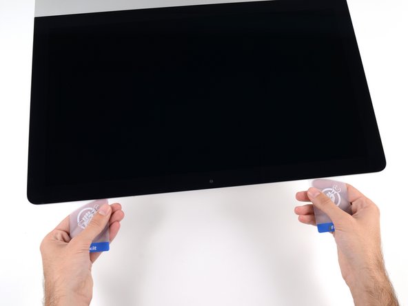
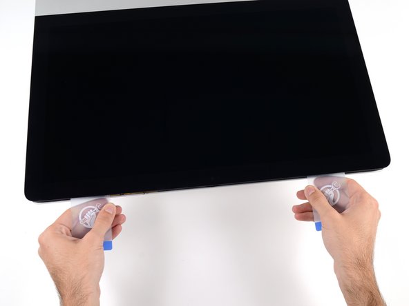
이 단계는 번역되지 않았습니다. 번역을 도와주십시오
-
Remove the following five Phillips screws holding the lower support bracket in place:
-
Four 3.2 mm screws
-
One 1.7 mm screw
-
-
이 단계는 번역되지 않았습니다. 번역을 도와주십시오
-
Gently pull the right speaker cable connector straight down and out of its socket on the logic board.
-
-
이 단계는 번역되지 않았습니다. 번역을 도와주십시오
-
Remove the two 10 mm T10 Torx screws securing the right speaker to the rear enclosure.
-
-
이 단계는 번역되지 않았습니다. 번역을 도와주십시오
-
Insert the tip of a spudger between the right speaker and the antenna cable, running it down the right side of the speaker to de-route the cable from its channel.
-
-
이 단계는 번역되지 않았습니다. 번역을 도와주십시오
-
Tip the right speaker forward out of the rear enclosure, about 1 cm.
-
Pull the speaker straight up and remove it from the iMac.
-
-
이 단계는 번역되지 않았습니다. 번역을 도와주십시오
-
Remove the following T10 Torx screws securing the hard drive brackets to the iMac:
-
Two 21 mm screws
-
One 9 mm screw
-
One 27 mm screw
-
-
이 단계는 번역되지 않았습니다. 번역을 도와주십시오
-
Use the tip of a spudger to push each side of the power button cable connector and gently walk it out of its socket.
-
-
이 단계는 번역되지 않았습니다. 번역을 도와주십시오
-
Use the tip of a spudger to push each side of the power supply control cable connector and gently walk it out of its socket.
-
-
이 단계는 번역되지 않았습니다. 번역을 도와주십시오
-
Remove the two 7.2 mm T10 Torx screws securing the power supply to the rear enclosure.
-
-
이 단계는 번역되지 않았습니다. 번역을 도와주십시오
-
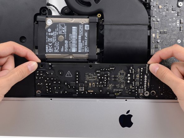
Pull the power supply slightly up and out from the rear enclosure.
-
Rotate the power supply counterclockwise, lifting the right side up about an inch higher than the left.
-
-
이 단계는 번역되지 않았습니다. 번역을 도와주십시오
-
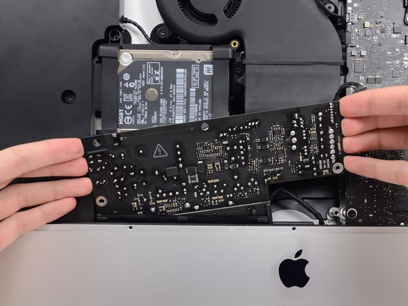
Slide the power supply to the right to clear the screw posts on the rear enclosure.
-
-
이 단계는 번역되지 않았습니다. 번역을 도와주십시오
-
Rock the power supply forward and remove it from its recess in the rear enclosure.
-
-
이 단계는 번역되지 않았습니다. 번역을 도와주십시오
-
Squeeze the tab on the back side of the DC power cable connector and pull it straight out of its socket on the back of the logic board.
-
-
이 단계는 번역되지 않았습니다. 번역을 도와주십시오
-
Use the flat end of a spudger to press the clip on the side of the AC inlet cable connector inward.
-
While pressing on the release clip with the spudger, grasp the AC inlet cable, and pull the connector straight out of its socket.
-
-
이 단계는 번역되지 않았습니다. 번역을 도와주십시오
-
Gently pull the fan cable connector straight out of its socket on the logic board.
-
-
이 단계는 번역되지 않았습니다. 번역을 도와주십시오
-
Remove the three 10 mm T10 Torx screws securing the fan to the rear enclosure.
-
-
이 단계는 번역되지 않았습니다. 번역을 도와주십시오
-
Remove the 7.3 mm T8 Torx screw securing the hard drive tray to the rear enclosure.
-
-
이 단계는 번역되지 않았습니다. 번역을 도와주십시오
-
Gently pull the left speaker cable straight out of its socket on the logic board.
-
-
이 단계는 번역되지 않았습니다. 번역을 도와주십시오
-
De-route the left speaker cable by pulling it straight up out of the retaining clip in the back of the rear enclosure.
-
-
이 단계는 번역되지 않았습니다. 번역을 도와주십시오
-
Similarly to the previous step, de-route the SATA and power cables by pulling the braid straight up out of the retaining clip.
-
-
이 단계는 번역되지 않았습니다. 번역을 도와주십시오
-
Peel up the piece of tape connecting the left speaker connector to the SATA power and data cables.
-
-
이 단계는 번역되지 않았습니다. 번역을 도와주십시오
-
Flip up the metal retaining bracket on the FaceTime camera cable connector.
-
Pull the FaceTime camera cable straight out of its socket on the logic board.
-
-
이 단계는 번역되지 않았습니다. 번역을 도와주십시오
-
Remove the two 4.0 mm T5 Torx screws securing the four antenna connectors to the AirPort/Bluetooth card.
-
-
이 단계는 번역되지 않았습니다. 번역을 도와주십시오
-
Disconnect all four antenna connectors by prying them straight up from their sockets on the AirPort/Bluetooth card.
-
-
이 단계는 번역되지 않았습니다. 번역을 도와주십시오
-
Use the flat edge of a spudger to pry the headphone jack cable connector from its socket on the logic board.
-
-
이 단계는 번역되지 않았습니다. 번역을 도와주십시오
-
Remove the following T8 Torx screws securing the exhaust duct to the rear enclosure:
-
Two 6.2 mm screws
-
Two 4.7 mm screws
-
-
이 단계는 번역되지 않았습니다. 번역을 도와주십시오
-
Remove the four 7.3 mm T8 Torx screws securing the logic board to the rear enclosure.
-
-
이 단계는 번역되지 않았습니다. 번역을 도와주십시오
-
You can use a USB flash drive and/or ethernet cable to ensure the logic board is seated correctly while you screw it in.
-
-
이 단계는 번역되지 않았습니다. 번역을 도와주십시오
-
Slightly lift the rightmost side of the SSD and firmly slide it straight out of its socket on the logic board.
-


다른 11명이 해당 안내서를 완성하였습니다.


댓글 6개
There’s no PCIe slot on the EMC 2889 motherboard???
It depends!
If you got a SATA drive’d model then that is correct! No PCI/e SSD slot.
But! If you got a Fusion Drive’d model, or one which has a SSD then your logic board DOES have the PCIe SSD slot
Dan -
Hi, for iMac 16.2 no Fusion Drive and no HD/SSD, there aren’t EMC for upgrade/repair? I’ve searched in all place, OWC Aura Pro 2X isn’t compatible with 16.1 and 16.2… I think this model can be only repaired or upgraded (maybe only repaired) in Apple Store. This is right? Best regards
Both the 2015 21.5” iMacs iMac16.1 & iMac16.2 (4k) offer a 8.0 GT/s PCIe x4 custom blade SSD connector on SSD only model as well as with the Fusion Drive model. A straight HDD system will not have the slot hardware!
The problem you are seeing here is the 21.5” A1418 only supported PCIe 2.0 x4 where the 27” A1419 supported PCIe 3.0 x4. The older SSD’s Apple used where PCIe 2.0 x2.
Apple didn’t use the PCIe 2.0 x4 SSD very long which is why you need to stick with the real Apple SSD in this series requires.