iMac 24" A1200 power supply pinout?
Hi all!
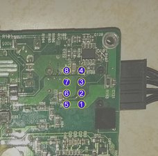
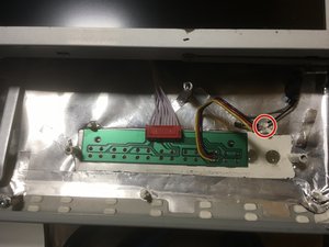
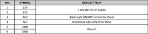
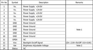
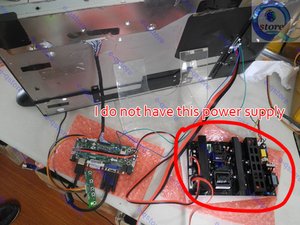
A friend of mine gave me a broken imac 24". I would like to recycle the power supply for another project, however i don't know the pinout, well i could easily find the Vcc with voltmeter. I just need to know which pin will switch on the unit, and if it's a "connect to Vcc" or "connect to ground" system.
Here some more
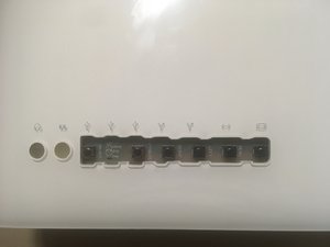
ref. SADP-220AF (A1200)
24v@4A and 12V@10,3A
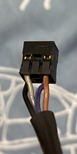
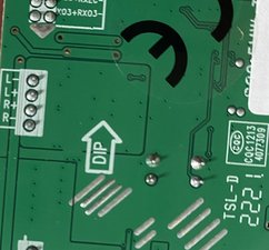
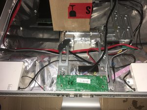
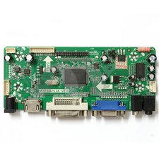
A few pics


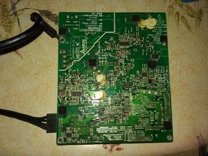

Cheers!
좋은 질문 입니까?
점수
0