Hi @luke ,
Here is a link to the User/Installation manual (found from this webpage).
The wiring (p.11) seems to indicate that the remote controls the amount of current to the fan motor and the lights. A resistor burning out indicates excess current, usually caused by a short circuit (s/c) or a s/c to Earth.
With the fan disconnected from everything, use an Ohmmeter to check the resistance between the white wire from the fan and:
the black wire from the fan. (this is the fan motor - I think)
the blue wire (or black/white stripe) from the fan. (this is the lights - I think)
The motor may read a low resistance as might the lights but not a s/c.
and also between the green/yellow stripe wire from the fan and:
the black wire from the fan
the blue wire (or black /white stripe)from the fan
This will test if there is a connection between either of the two circuits, (motor and light) and earth (which there shouldn't be).
If the fan motor is the problem, as it is less than 12 months old it may be that it is still covered by the Limited Lifetime Motor Warranty. You could try contacting Hunter fans at social@help.hunterfan.com. and ask if this is the case. It never hurts to ask.
As an aside, if you haven't already, it might be advisable to have one (or more) of these RCD (Residual Current Device - Safety Switch) installed in the power outlet and light circuits of the premises, as a safeguard against any future electrical problems. If it was a leakage to earth problem, the RCD would've tripped, isolating the circuit.
Hi @luke ,
The readings for the motor seem rather high. I was expecting somewhere in the range of 30-200 Ohms for the motor winding. It may be that the run winding has burnt out and that you're reading leakage resistance through the capacitor / start winding. On starting most of the current goes through a lower resistance start winding, and if the start winding cut out switch was s/c for instance the start winding would still be "in circuit' and therefore drawing excess current burning out the resistor. This is only speculation on my part.
To find out how it is wired you'd have to dig deeper into the fan. Personally I'd go the warranty route first , if still applicable.
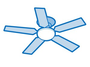
I don't know how your particular fan motor is wired but I imagined that it would be something similar to the image below. Speed being controlled by the receiver box regulating the current supply to the fan
,
What is not shown in this image is that usually there is a centrifugal switch in the motor that o/c the start winding circuit (Aux winding in this particular image) when the motor gets up to speed.
With the light circuit, I may have misLED (pun intended) you. I overlooked that the fan has LED lights which may account for the high reading. You can't really test LEDs with an Ohmmeter accurately. You could try the diode test in the DMM if there is one (reverse the leads to see if it makes a difference) but again it depends how it is set up. The only good thing about what you tested is that there wasn't a very low resistance reading which could cause excess current to flow.


댓글 12개
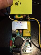
Hey, this is a different question. Would you be able to post photos of that big yellow capacitor in the controller?
The metal is blocking the text so I am unable to figure out it's capacitance. Not sure if you even have this after 2 years.
I am trying to build a DIY WiFi fan controller and I need to figure out the capacitance. Not trying to open up mine.
Sarabveer Singh 의
hi, i have the same one. its a 5uF cap. Are you trying to use a sonoff iFan03 by any chance?
Matthew Dezzi 의
@Matthew Dezzi Yea I was trying to use an iFan03, but I put off the project for a later time.
Sarabveer Singh 의
@sarabveer I am doing the same. However, there are three capacitors in the hunter receiver. 2x 5uF and 1x 1.8uF, so i'm not sure what to use in the ifan. Here's some pictures of mine: https://imgur.com/a/blH05a3
Matthew Dezzi 의
@Matthew Dezzi I never noticed there are 2 5uF caps.
In that case, it seems we would need 2 5uF caps in the iFan03 as well, just as shown in this video https://www.youtube.com/watch?v=XCEPluSv...
Sarabveer Singh 의
댓글 7개 더보기