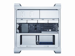
Mac Pro Won't turn on
I heard the click but will turn on.
좋은 질문입니까?
점수
7
평판: 295
![]() 2
2
![]() 2
2
I heard the click but will turn on.
좋은 질문입니까?

평판: 852.5k
![]() 1.4k
1.4k
![]() 959
959
![]() 2.4k
2.4k
@fachill
check a few things that Apple recommended:
No Power/Dead Unit
Unlikely cause: Optical drive(s), hard drive(s), fans, memory, processors, PCIe cards, speaker, AirPort card, Bluetooth card
Quick Check
No Power/Dead Unit
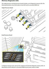
Reseat all DIMMs. Refer to Memory Diagnostic LEDs.
No power
Verify power source.
No front panel power/sleep LED
Verify power cable.
No startup chime
No Image on external display
No HD
Reset SMC by unplugging the AC power cord for 15 seconds. Reconnect the power cord without pressing the power button. After 5 seconds press the power button and verify that the the computer turns on.
No fans spin
No light if Caps Lock pressed
Non-operational
Reset RTC.
Deep Dive
Check
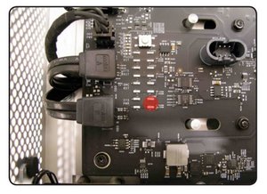
1. Verify that connection between power supply and backplane board is undamaged and secure. Verify that power button and front panel board cable connections to the front panel board are undamaged and secure. See Functional Overview.
Yes Go to step 2
No Reseat all connectors and retest.
2. Connect AC power cord to the computer. Verify the 5V STBY LED illuminates when you press the DIAG button on the backplane board.
Yes STBY LED illuminates, but computer won’t power ON.
Go to step 4.
No Suspect power supply failure. Replace power supply and go to step 3.
3. Verify the 5V STBY LED illuminates when you press the DIAG button on the backplane board.
Yes Issue resolved.
No Go to step 5.
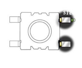
4. Disconnect the front panel board. Momentarily jumper the pictured SYS_PWR solder pads on the backplane board. Verify the computer turns ON.
Yes Front panel board or power button failure. For front panel board, use code M01. To verify power button, go to Power Button Stuck.
No Go to step 5.
5. Reduce computer to minimal configuration. See Minimum Configuration Testing. Verify the 5V STBY LED illuminates when you press the DIAG button on the backplane board.
Yes Suspect a module that has been removed. Reinstall modules until symptom reappears. Replace affected module. Then go to step 6.
No Replace backplane board and retest.
6. Reconnect the processor board without processors. Press power button and verify computer turns ON. You can tell if the computer has started up by fans and LEDs. There is no other activity since there are no processors.
Yes Add processor A and retest. If computer power remains stable, the power issue is resolved.
No Go to step 1.
Minimum Configuration Testing
The following procedure can help you troubleshoot a “No Power” or other startup related symptom. The method gradually builds up the system from a minimum configuration and verifies expected behaviors at each step. This approach helps determine which modules function together. The goal is to identify which module(s) cause a symptom to recur when they are added. This method may also help you discover a loose or faulty cable or connector. If you encounter unexpected behavior during a step, you should investigate the last module you re-installed. Backtrack to the previous step, remove the last installed module, and re-verify the expected behavior.
Note: Minimum configuration testing may not be practical for every repair. Refer to other troubleshooting sections in this manual for additional direction.
Take Mac Pro Down to Minimum Configuration
1. Remove the following items from the Mac Pro:
• Hard drives/solid state drives
• Optical drives
• Processor tray and processor board (containing processors, processor heatsinks, and memory)
• PCIe cards
• AirPort card
• Bluetooth card
• Battery
• PCIe fan
• Processor cage (including fans)
• Front panel board
Disconnect all cables from the backplane board, except the power supply.
2. Attach a known good power cord from a known good AC source to the Mac Pro.
Note: When connecting the Mac Pro to AC power, verify that the LEDs for OVTMP CPUA and OVTMP CPUB briefly flash red (less than 0.5 sec). The LEDs are located under hard drive bay 1 on the backplane board. If they do not illuminate briefly, there is an issue with either the power supply or the backplane board. Generally speaking, power supplies can be affected by issues more than other modules. If you suspect a power supply has failed,verify it in another Mac Pro if available, before replacing any modules.
Note: The OVTMP CPUA and OVTMP CPUB LEDs on a properly functioning Mac Pro will also momentarily flash red immediately after the Mac Pro is disconnected from AC power.

3. Press the DIAG button, and verify 5V STBY LED (amber) illuminates.
Expected behavior:
5V STBY LED illuminates, confirming power to the backplane board. If the LED does not illumuniate, suspect power supply or backplane board failure.
4. Disconnect AC power cord. Reinstall processor cage with fans and processor board. Do not reinstall processor(s), heatsinks, or memory.
Notes:
• Verify no bent pins on processor connector or mating connector of processor board and backplane board.
• Verify no grime or foreign debris is causing contact issues on processor connectors, and connectors on processor board and backplane board.
5. Connect AC power cord. Press the DIAG button to verify the 5V STBY LED illuminates. This is a verify step, as you’ve added modules since previous step.
Expected behavior:
5V STBY LED illuminates, confirming power to the backplane board. If the LED does not illuminate, suspect power supply or backplane board failure.
6. Momentarily jump the SYS_PWR solder pads to turn ON the Mac Pro.
Expected behavior:
• Front and rear processor cage fans (and PCIe fan, if installed) should spin slowly
• One red-colored error LED illuminates on the processor board (next to the memory slots).
Notes:
• The solder pads are at the same location where the power button would be.
• To help troubleshoot processor issues, check the related CPU Error LED. See “Processor
Diagnostic LEDs.”
7. Press and hold the DIAG button.
Expected behavior:
• PSU PWROK (green), 5V STBY (amber), EFI DONE (green), GPU OK (green) LEDs illuminated
• No startup tone
• Front and rear processor cage fans (and PCIe fan, if installed) should spin slowly
8. Disconnect AC power cord.
At this point, to make testing easier try powering on the computer using a known good front panel board, power button, and cable, instead of jumpering SYS_PWR solder pads.
9. Reconnect internal speaker. Reinstall a processor and heatsink in processor A connector, and one known good and compatible Apple memory DIMM in slot 1.
Notes:
• The Mac Pro won’t start if you use processor B only on a dual-processor board. Use processor A connector.
• Verify no damaged pins on DIMM or processor connectors or mating connector of processor board and backplane board.
• Verify no damaged heatsink thermal sensor and fan connector pins or mating connector on the processor board. If there is damage, all Mac Pro fans will ramp to 100% when power ON.
• Verify no grime or foreign debris is causing contact issues on DIMM, processor connectors, and connectors on processor board and backplane board.
10. Connect AC power cord. Press the DIAG button to verify the 5V STBY LED illuminates. (This is a verification step, as you’ve added modules since previous step.)
11. Power Mac Pro ON either by PWR_ON solder pads or front panel board.
Expected behavior:
• The red-colored error LED on the processor board next to the memory slots at processor A should flash once only as the Mac Pro powers on.
• Startup tone heard (if not, reset PRAM and retest)
• Front and rear processor cage fans (and PCIe fan, if installed) should spin slowly
Notes:
• If using dual-processor board, both the LEDs next to the memory slots should flash once only.
• You can test both processors independently using processor A connector only.
12. Disconnect AC power cord. Install a known-good hard drive with a compatible/bootable Mac OS installed.
Notes:
• Verify no damaged SATA data or power pins on drive and mating connector on backplane board.
• Verify no grime or foreign debris is causing contact issues on SATA data or power pins on drive and mating connector on backplane board.
13. Connect AC power cord. Power Mac Pro on by PWR_ON solder pads or front panel board.
Expected behavior:
Listen for sound of hard drive boot. If no indication of hard drive boot, try drive in another bay.
Note:
Shortly after boot start, verify that a red-colored LED is illuminated within the optical audio-out jack at the rear of the Mac Pro. If so, software drivers have been loaded.
14. Disconnect AC power cord. Install a known good compatible PCIe graphics card into slot 1 and attach a known good display.
Notes:
• Verify no damaged PCIe pins on the video card and mating PCIe connector on backplane board.
• Verify no grime or foreign debris is causing contact issues on the video card and mating connector on backplane board.
15. Connect AC power cord. Power Mac Pro ON either by PWR_ON solder pads or front panel board.
Expected behavior:
• Listen for sound of hard drive boot.
• Verify good uncorrupted video on display.
Let us know what you find out.
이 답변이 도움이 되었나요?
Thank you so much for the info.
평판: 25
![]() 1
1
6. Momentarily jump the SYS_PWR solder pads to turn ON the Mac Pro.
—-still no power
이 답변이 도움이 되었나요?
did you ever get it to work? currently dealing with the same problem
4 years later, did you figure it out?
Help! I have the exact same problem. Followed all the step by step troubleshooting. Replaced the backplane board, power supply and front panel board. Also checked battery in the board. I’m completely baffled
@fgrjbf2lypbaa3x power cable?

평판: 13
![]() 1
1
Also consider this response where a defective memory riser could lead to DIAG_LED 2 and 9 being lit. https://apple.stackexchange.com/a/437563...
이 답변이 도움이 되었나요?
지난 24시간: 14
지난 7일: 56
지난 30일: 172
전체 시간: 30,882
댓글 5개
What diagnostic lights are you getting?
mayer 의
I am getting no lights.
Faliere Dieujuste 의
I had a similar problem that took a lot of time and work to resolve. It suddenly wouldn't turn on when the power button was pressed. After pressing it several times, it finally turned on. A few days later, it would not turn on at all. I replaced the power button, but then the two OVTMP lights came on constantly. I tried replacing most of the other parts. The problem would not go away. I tried a reassembly from the ground up, beginning with hooking the motherboard to a power supply outside the case. The red lights blinked on and then off (passing the test). I then put it together one piece at a time and checked the red lights at each step. The red lights stayed on when I connected the small front board to the motherboard. I then unhooked the tiny connection for the power button and reconnected it (not sure what motivated me to try this). The red lights then blinked on and off. I finished putting the computer together, and it works fine. Not sure what this all means, but hopefully it might be helpful.
cinclodes 의
When I press power on button it give me red flash and won’t turn on please help me
Alpert 의
My problem was the Graphics card was busted, the Computer was actually turning on, I just couldn't see anything or hear anything. I managed to get a replacement Graphics Card and it works fine now.
Aidan Stewart 의