주요 콘텐츠로 건너뛰기

BeatsX Wiring Diagram on main board

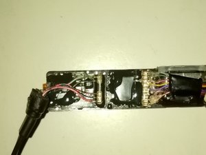
I have a BeatsX that is broken, and it’s not viable for me to fix it, so I decided to try to recycle it, making a wired one from the old speakers and control talk. Those are still fully functional. So in order to do this, I need a wiring diagram or at least the wiring color code for the Left speaker connector (the one with the control talk board), because I have no idea what wire should be connected to what. I’ll try to send an image for better visualization.

Block Image

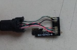
Update: I discover that the pink (first wire from bottom to top) is equivalent to the L+ on 3.5 mm jack standard, and the green (last wire from bottom to top) is the equivalent ground. But I still have no idea about the other wires. I tried the folowing:

  • Black on Ground
  • Red on M+ (microphone)
  • Blue on L+
  • But it didn’t work. I’m not able to discover what wire is what with a multimeter because I’m afraid I’ll break the control talk board if I do so. I tried this based on recommended YouTube videos. Here it goes another image (maybe better than the last one) for better understanding:

*

Block Image

이 질문에 답하기 저도 같은 문제를 겪고 있습니다

좋은 질문 입니까?

점수 0
댓글 1개

Sorry I haven’t seen any schematics or diagram which would explain what the connections are. Beats doesn’t offer anything and they don’t repair them either.

댓글 달기

답변 1개

가장 유용한 답변

@pedro2012 you can check the wires with a multimeter. Place one end on the connection on the board and then touch the wires on the drivers (speaker) or the mic. You will know which wire goes where by your meter showing continuity. If your meter does not have a continuity test, use the resistance scale. If you have trouble with that, post some images of your complete earbuds with the wires, earbuds etc., with your QUESTION so we can try and help you with it. 기존 질문에 이미지 추가하기

Videos like this one as well as this are always a great starting point.

해당 답변은 도움이 되었습니까?

점수 3

댓글 2개:

Hello! Thanks a lot, that really helped me to have a better understanding! Based on what he said in the video, I decided to test it, but I wasn’t able to connect successfully the control board to the 3.5 mm jack. I don’t even know if that’s possible, but I tried. The speakers are successfully connected, but the rest is still a mistery to me. I would take your advice and, with the multimeter, test what is what, but I’m afraid that, if I decide to disassembly the control talk board I’ll break it, so I’m trying almost all the combinations possible for the wiring, but I still got nothing, if you could help me, I’d be very grateful! I’ll edit the original post so you can know my progress. Thanks for your attention, I’m very grateful! :)

@pedro2012 where does that circuit board in your last picture connect to?

댓글 달기

귀하의 답변을 추가하세요

Pedro 님은 대단히 고마워 할 것입니다.
조회 통계:

24 시간 전: 1

7일 전: 5

30일 전: 13

전체 시간: 658