주요 콘텐츠로 건너뛰기

Find repair and detailed information for the Frigidaire Freezer FFFH20F3W*, a non-compact, standalone upright freezer with automatic defrost released in 2020, without a through-the-door dispenser or ice maker. This page covers information for model numbers matching the pattern FFFH20F3W*.

2 질문 전체 보기

Frigidaire FFFH20F3WW upright freezer green flashing light and beep

Hi.
I bought this freezer used/reconditioned a year ago and it worked for a while but then the green light below the door started flashing and beeping.
I opened up the inside front evaporator panel to find the whole evaporator totally frozen. I unplugged and let the freezer defrost with the door open. A day or two later I put the cover back on and plugged it back in and it worked for a day or so and then the green light started flashing and beeping once again.

I have not used this freezer since but recently decided to attempt a diy diagnosis/repair job.

I first started with the magnet and the reed switch to cycle through the freezers 4 options. With a clamp multimeter I was getting similar amp draws for the first 3 options but then then the 4th option (evaporator fan motor) I got 0 amps as my reading.

Everything at the back of the freezer seems fine. There doesn't seem to be any leaks, the condensor fan spins (when in test mode), the condensor is warm and I can hear it, no obvious damage.

So I decided to check the evaporator fan at the front. In order to access this you need to pry off the cooling tower and unplug the fan. There is also a white lead that is attached to the same wiring harness. I believe this is the thermostat/temp sensor as one end sits up behind the cooling tower and the other attaches to the top of the evaporator. ( I do not know how to check whether this is working)

Using a 9v battery, I checked the fan. It works fine.

I am about to check the defrost heater by using a multimeter on the ohms option. This will tell me whether thats working.

I have read that a good check is to find out whether the defrost thermostat is working by checking its continuity, putting it in a freezer and having it open/close etc. BUT i can't find one anywhere. All the photos I found are of a small round cased object that can often look visually broken with the top broken open. Anyway, this freezer does not have one, that I can locate!! Am I blind?!

The only other thing that I can think might not be working is the potenitometer behind the single knob that turns from cold to coldest.

I am at a loss as to what else to try/check. I'm happy to buy some repair parts but does anyone have any advice as to what my issue is?

Thanks in advance.

Update (02/08/24)

Block Image

Block Image

Block Image

Block Image

Block Image

Block Image

이 질문에 답하기 저도 같은 문제를 겪고 있습니다

좋은 질문 입니까?

점수 0
댓글 2개

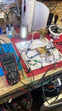
Defrost heater element read 56 ohms which would mean that it's still good

word for word andfrustration level matched. im bench testing this board tonight. if i find a solution im will post

댓글 달기

답변 2개

가장 유용한 답변

Hi @adhoc33589

According to the parts diagram for the freezer, the freezer has two thermostats, the defrost thermostat (part #21 system diagram) and the freezer temperature thermostat (part #21 Cabinet diagram).

This is confirmed by the wiring diagram for the freezer.

You may be looking for the wrong sort of defrost thermostat. The defrost thermostat and the freezer temperature thermostat used in the model seem to be a dual thermostat module setup of some description, judging by the fact that they both have the same part number i.e. Frigidaire part # 5304523788 (example only to show image of part). To me they both look more like regular NTC thermistor type sensors used in refrigerators/freezer etc rather than one of them looking like the usual round bi-metal defrost thermostat though.

Most thermistors used in refrigerators/freezer are of the NTC type i.e. negative temperature co-efficient. As the surrounding temperature increases, their resistance decreases. Unless there is a type number on the thermistor itself it would be hard to know what value resistance it should be at the given temperature. Here's an example showing the resistance/temperature chart of different model NTC thermsitors to show what I mean. These values are not for the thermostats used in your freezer as far as I know.

Based on the image and the parts diagrams the temperature thermostat would be the one mounted in the air column and the defrost thermostat would be the one attached to the evaporator unit

Disconnect the thermostat cable and then connect an Ohmmeter across the two black wires (defrost thermostat) and then the two white (grey?) wires (temperature thermostat) of the thermostat cable plug and check what resistance you measure. They both should not measure either open circuit (OL) or short circuit (0.00 Ohms). As to what they should measure I don't know.

If the defrost thermostat tests OK i.e. not open or short and the resistance value seems reasonable, then use the wiring diagram as it details how to get into the defrost mode so that you can check if the defrost heater is getting power or not. The defrost heater is connected to the main control board J1 plug socket pins 1 & 8. Be safety aware when testing for the heater power as it operates at 120V AC.

If there's no power for the heater at the control board connectors when testing during the defrost mode there may be a problem with the control board part # 5304529281 (supplier example only). Search online for the part number only to find suppliers that suit you best.

Another check would be to ensure that the drain tube leading from under the evaporator unit to the evaporator pan under the cabinet near the condenser coils and compressor etc is not blocked, preventing the defrost meltwater from draining away to be evaporated naturally. Usually an indicator of this is water overflowing into the compartment during or immediately after the defrost cycle. If it is blocked then the water could not drain away and would gather and refreeze and build up again when the defrost cycle ended and the freezer went back to normal operating temperatures. Over time this could be the cause of ice building up over the evap unit and it could even ice over the fan preventing it from operating.

As an aside if you measured 56 Ohms between pins 1 & 4 of the defrost heater cable plug then the heater element and the two thermal fuses electrically connected inline either side of the heater i.e. one on the Active side and one on the Neutral side of the heater are OK. The fuses are designed to go permanently open circuit if the temperature is >72°F.

해당 답변은 도움이 되었습니까?

점수 2

댓글 14개:

OK, so last night I put everything loosely back together again and fired her up.

The green light stays constant (as it would normally) but there is no action. The freezer is on, the light inside comes on when the door is open and when I put it into test mode, it fires up. But only in test mode.

In test mode, the evaporator coil began to get cold and the defrost heater got hot, which would indicate that the heater is working.

I just disconnected and tested the resistance of the defrost thermostat and temp thermostat and did get readings of around 13 Kiloohms. The multimeter was set to auto and so chose the kohms option. When I changed the range to ohms, i got OL for both thermostats.

I also checked the potentiometer and got a variable reading when the knob was turned. I had probes on the orange and yellow wire.

Any further ideas/suggestions in light of this info? What would be preventing the freezer from automatically firing up? I was really hoping it was a faulty thermostat!

Also, thanks so much for your help

@adhoc33589

Just verifying that you performed two separate tests whilst in service mode i.e. Test ! and then Test 2 and not that the heater turned on when the compressor was still running?

If you exited Test mode as described and it didn't start as it should then perhaps check if the temperature control potentiometer voltages as seen on control board J3 connector are as shown.

I can only think of two reasons why it doesn't start when it should:

1. The temp control pot is indicating that it is cold enough so no need to run the compressor to cool things down to the set temp. - did you test between the brown and orange wire or even the brown and yellow wire, also did you unplug it from the control board when you tested it to prevent incorrect measurement due to a parallel circuit connection in the control board?

2. For some reason it may be still in defrost mode for some reason. Did you try a manual defrost when not in test mode? If it doesn't work then it may still be in this mode. Stupid thought perhaps by try waiting for 67 minutes and check if it turns on after leaving it in normal mode.

After entering service mode, I cycled through all 4 tests.

I followed this guide on YouTube - https://www.youtube.com/watch?v=vN5hvM2k...

I did not actually check whether Test 2 : Defrost Heater, started the heater. I followed the video and took Amp readings behind the freezer.

The only test that didn't receive any Amp draw at the back was for the evaporator fan. However, I checked the fan and it is fine.

I disconnected the pot and tested the resistances. The only readings I got were between the orange and yellow wires. No other combo received any reading, just OL. I assumed this was maybe the wiper?!

to answer your first question - I'm pretty sure that the heater came on whilst in Test 1 whilst the compressor and condensor fan were running behind. I will double check this.

I will also try manually activating defrost with the 5 magnetic touches and see what happens.

I can confirm that all tests worked as they should.

First test - fan and compressor turned on.

2nd - defrost heater started.

3rd - interior bulb on

4th - evaporator fan started.

Unsure as to how to check voltages on pot which indicate +5v.

Maybe the lack of readings on the pot wires would indicate a problem?

@adhoc33589

If you didn't get any resistance reading when using an Ohmmeter to directly measure the temperature control pot between the brown and yellow wire terminals of the pot (or between the brown and orange wire terminals) then the pot is faulty.

You should get a resistance reading when measuring between the yellow and the brown wire terminals on the pot as this is the full range measure of the pot and not just part of it as it is when measuring between the yellow and the orange. Make sure that it is disconnected from the harness cable or whatever and measure on the pot itself.

The pot is used as a voltage divider i.e. current flows from the yellow to the brown and also from the yellow to the orange and depending on where the orange wire which is connected to the wiper is along the coil resistor or whatever it is in contact with e.g. it could be a graphite resistor will alter the amount of voltage being "seen" by the control board indicating at what temp you would like the freezer set to. The voltage signal value = the desired temp setting or even "off".

It may be and I don't know if this is correct, that if the control board "sees" the full 5V which it will if the section of the pot between the orange and the brown is open circuit then this might indicate the "off" position on the pot so maybe that's why it doesn't turn on

For example there is 5V DC supplied to the pot by the control board but essentially the 5V is divided into 2 voltages i.e. the voltage drop on the pot between the yellow wire and the orange wire and the voltage drop on the pot between the orange and the brown e.g. it could be in the ratio of 3:2 or 4:1 or 1:4 or even 5:0 if this does indicate the off position etc depending where along the pot the wiper has been positioned by the user adjusting the temp setting.

The voltage value on the orange wire is translated into a temperature value and this is compared to the resistance value of the temp sensor in the air column which is also translated into a temperature value so the control board knows whether to cool things down further to what you want or turn off as it is cold enough.

This is also with the proviso that it is operating withing the standard upper and lower preset temp limits for your freezer of 4°F → -4°F. All the temp control pot does is allow you to vary the temp within this range or to turn the unit off.

댓글 9개 더보기

댓글 달기

bench tested with alternate components to make sure the board was doing what it was suppposed to. in place of the reed switch i used another fridge door switch. to make sure i could put it in diagnostic mode flawlessly. this was my setup i also used a different potentiometer which may have been the issue along. with the three leads im assuming that if one was signal . that the potentiometer has a crappy connect5ion within itself. it worked good on my bench so hopefully its the same when i reinstall it

Block Image

Block Image

해당 답변은 도움이 되었습니까?

점수 0
댓글 달기

귀하의 답변을 추가하세요

Ad Hoc 님은 대단히 고마워 할 것입니다.
조회 통계:

24 시간 전: 4

7일 전: 49

30일 전: 217

전체 시간: 853