이 안내서에는 최근 변경 사항이 더 있습니다. 최신 비검증 버전으로 전환하십시오.
소개
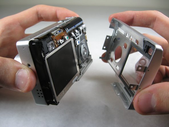
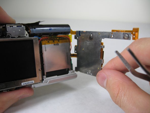
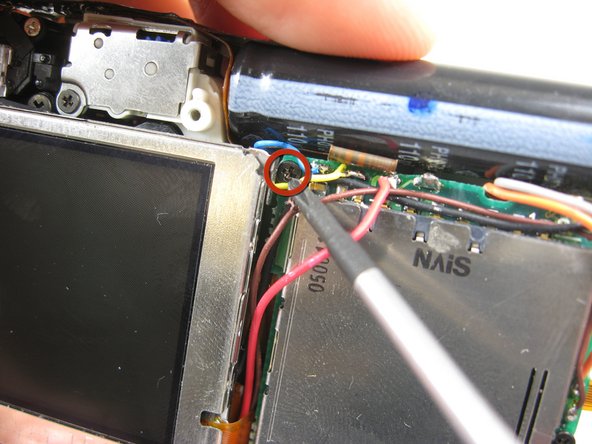
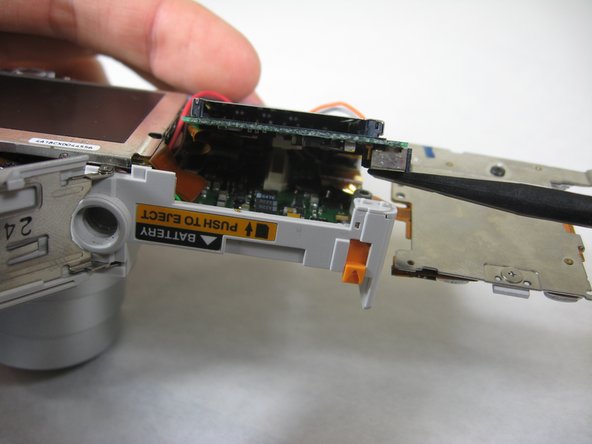
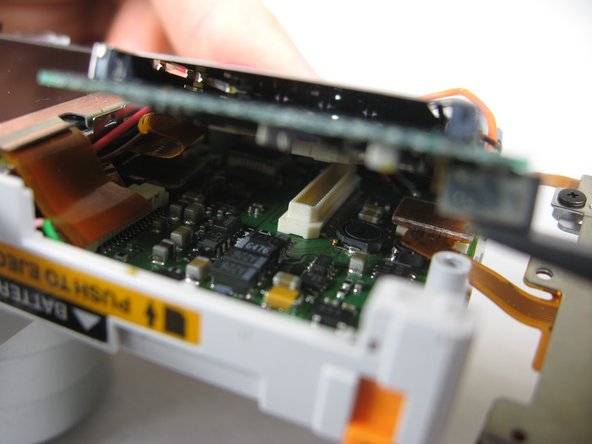
In this guide you will learn how to remove the SD card circuit board to access the logic board. To access the logic board, you will need to unsolder two leads. For soldering instructions, please refer to steps 1 through 6 of this soldering guide.
필요한 것
-
-
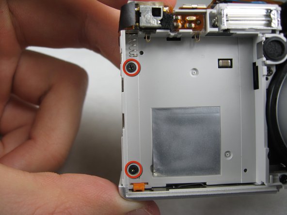
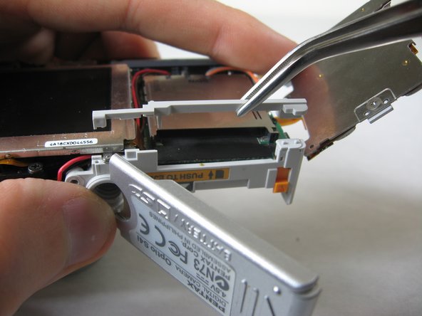
Remove the following screws:
-
Two silver 3.15mm Phillips #00 screws on the right side of the camera
-
Two silver 2.08mm Phillips #00 screws on the left side of the camera
-
-
-
-
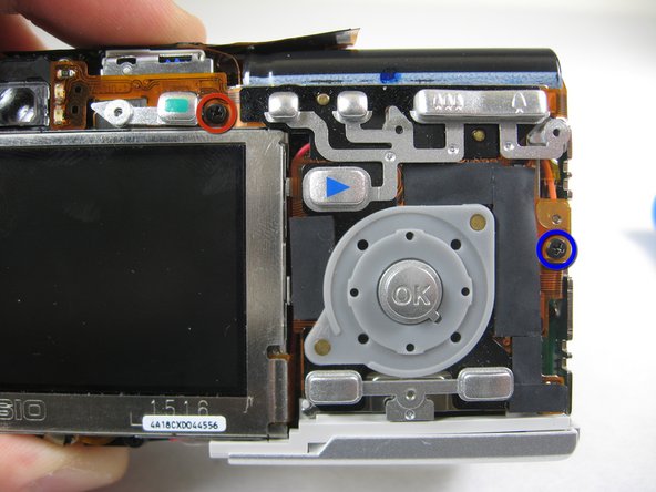
On the front of the camera, in battery case, remove screws indicated:
-
Two black 2.05mm Phillips #00 screws
-


To reassemble your device, follow these instructions in reverse order.
To reassemble your device, follow these instructions in reverse order.
팀

Cal Poly, Team 4-29, Regan Winter 2011 Cal Poly, Team 4-29, Regan Winter 2011 회원
CPSU-REGAN-W11S4G29
3 회원들
안내서 10개 작성하였습니다