이 버전에는 잘못된 편집 사항이 있을 수 있습니다. 최신 확인된 스냅샷으로 전환하십시오.
필요한 것
-
-
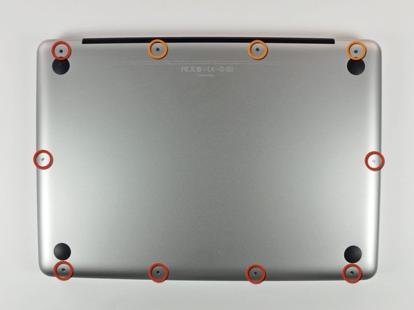
하단 케이스를 MacBook Pro 13" Unibody에 고정하는 다음 나사 열 개를 풀어주세요:
-
3mm 십자 나사 일곱 개
-
13.5mm 십자 나사 세 개.
-
-
이 단계는 번역되지 않았습니다. 번역을 도와주십시오
-
Use the flat end of a spudger to lift the battery connector up out of its socket on the logic board.
-
-
이 단계는 번역되지 않았습니다. 번역을 도와주십시오
-
Use a spudger to pry the fan connector out of its seat, and straight up off the logic board.
-
-
이 단계는 번역되지 않았습니다. 번역을 도와주십시오
-
Remove the following three screws securing the fan to the upper case:
-
One 6.5 mm Phillips.
-
One 5.5 mm Phillips.
-
One 4.5 mm Phillips.
-
-
이 단계는 번역되지 않았습니다. 번역을 도와주십시오
-
Grab the plastic pull tab secured to the display data cable lock, and rotate it toward the DC-in side of the computer.
-
Pull the display data cable connector straight away from its socket, towards the DC-in side of the computer.
-
-
-
이 단계는 번역되지 않았습니다. 번역을 도와주십시오
-
Remove the following two screws securing the display data cable bracket to the upper case:
-
One 7 mm Phillips.
-
One 5 mm Phillips.
-
Lift the display data cable bracket out of the upper case.
-
-
이 단계는 번역되지 않았습니다. 번역을 도와주십시오
-
Use the flat end of a spudger to pry the subwoofer and right speaker connector up off the logic board.
-
-
이 단계는 번역되지 않았습니다. 번역을 도와주십시오
-
Pull the camera cable connector toward the optical drive to disconnect it from the logic board.
-
-
이 단계는 번역되지 않았습니다. 번역을 도와주십시오
-
Use the flat end of a spudger to pry the optical drive, hard drive, and trackpad cable connectors up off the logic board.
-
-
이 단계는 번역되지 않았습니다. 번역을 도와주십시오
-
Use your fingernail or the tip of a spudger to flip up the cable retaining flap on the ZIF socket for the keyboard ribbon cable.
-
Use your spudger to slide the keyboard ribbon cable out of its socket.
-
-
이 단계는 번역되지 않았습니다. 번역을 도와주십시오
-
Peel the small strip of black tape off the keyboard backlight ribbon cable socket.
-
-
이 단계는 번역되지 않았습니다. 번역을 도와주십시오
-
Use the tip of a spudger to flip up the cable retaining flap on the ZIF socket for the keyboard backlight ribbon cable.
-
Use your spudger to slide the keyboard backlight ribbon cable out of its socket.
-
-
이 단계는 번역되지 않았습니다. 번역을 도와주십시오
-
Use the flat end of a spudger to pry the battery indicator cable connector up off the logic board.
-
-
이 단계는 번역되지 않았습니다. 번역을 도와주십시오
-
Use the tip of a spudger to pry the microphone off the adhesive attaching it to the upper case.
-
-
이 단계는 번역되지 않았습니다. 번역을 도와주십시오
-
Remove the following screws:
-
Five 3.1 mm Phillips.
-
Two 3.9 mm Phillips.
-
Two 7 mm Phillips from the DC-in board.
-
-
이 단계는 번역되지 않았습니다. 번역을 도와주십시오
-
Remove the following Tri-point screws securing the battery to the upper case:
-
One 5.5 mm Tri-point screw.
-
One 13.5 mm Tri-point screw.
-
Lift the battery out of the upper case.
-
-
이 단계는 번역되지 않았습니다. 번역을 도와주십시오
-
Lift the logic board from its left edge and raise it until the ports clear the side of the upper case.
-
Pull the logic board away from the side of the upper case and remove it, minding the DC-in board that may get caught.
-
-
이 단계는 번역되지 않았습니다. 번역을 도와주십시오
-
Remove the four 8.5 mm Phillips screws securing the heat sink to the logic board.
-
다른 54명이 해당 안내서를 완성하였습니다.
댓글 4개
After completing this process and reapplying thermal paste on my CPU and GPU, CPU Core 1 & 2 temperature sensors were not being read. As a result, my fan was not operating and the CPU diode temperature jumped to >100C.
To fix this I had to reset the SMC (System Management Controller). For this model it is done by holding done Shift+Control+Option and pressing the power button while the computer is off.
I have OS X 10.8.5 running. I also replaced my battery at the same time as reapplying thermal paste. No idea if that affected the temperature sensors.
Followed this guide to change thermal paste on CPU & GPU, all worked fine, now I have >10°C difference. I had a problem on a screw that wore out, solved by cutting a piece of motherboard. I recommend following this guide alongside a youtube guide video, if you are not sure on how to unplug some cables (like in which direction to pull). And as always, double (triple possibly) check that you have reconnected all cables, otherwise you’ll have to go through all of this again.
Well, my computer no longer turns on...reconnected all the cables, was very cautious and followed all steps and now it won't power on...it will charge, just won't power on anymore
me 2 Jarvis.any luck?
TheDoit123 - 답글


