이 버전에는 잘못된 편집 사항이 있을 수 있습니다. 최신 확인된 스냅샷으로 전환하십시오.
필요한 것
-
이 단계는 번역되지 않았습니다. 번역을 도와주십시오
-
Use your fingers to push both battery release tabs away from the battery, and lift the battery out of the computer.
-
-
이 단계는 번역되지 않았습니다. 번역을 도와주십시오
-
Remove the three identical 2mm Phillips screws from the memory door.
-
Lift the memory door up enough to grip it and slide it toward you, pulling it away from the casing.
-
-
이 단계는 번역되지 않았습니다. 번역을 도와주십시오
-
Remove the two 2.8 mm Phillips screws in the battery compartment near the latch.
-
-
이 단계는 번역되지 않았습니다. 번역을 도와주십시오
-
Remove the following 6 screws:
-
Two 10 mm T6 Torx screws on either side of the RAM slot.
-
Four 14.5 mm Phillips screws along the hinge.
-
-
이 단계는 번역되지 않았습니다. 번역을 도와주십시오
-
Remove the four 3.2 mm PH00 Phillips screws on the port side of the computer.
-
-
이 단계는 번역되지 않았습니다. 번역을 도와주십시오
-
Rotate the computer 90 degrees and remove the two 3.2 mm Phillips screws from the rear of the computer.
-
-
이 단계는 번역되지 않았습니다. 번역을 도와주십시오
-
Rotate the computer 90 degrees again and remove the four 3.2 mm Phillips screws from the side of the computer.
-
-
이 단계는 번역되지 않았습니다. 번역을 도와주십시오
-
Lift up at the rear of the case and work your fingers along the sides, freeing the case as you go. Once you have freed the sides, you may need to rock the case up and down to free the front of the upper case.
-
There are four plastic clips above the DVD slot, and another above and to the left of the IR sensor. These clips can be very difficult to disengage without prying. They can also be difficult to re-engage during reassembly.
-
-
-
이 단계는 번역되지 않았습니다. 번역을 도와주십시오
-
Disconnect the trackpad and keyboard ribbon cable from the logic board, removing tape as necessary.
-
Remove the upper case.
-
-
이 단계는 번역되지 않았습니다. 번역을 도와주십시오
-
Use the flat end of a spudger to disconnect the orange SuperDrive ribbon cable from the logic board, removing tape as necessary.
-
-
이 단계는 번역되지 않았습니다. 번역을 도와주십시오
-
Remove the following 4 screws:
-
Two 3.3 mm silver Phillips screws on either side of the SuperDrive.
-
One 4.7 mm silver T6 Torx screw from the top left corner of the drive.
-
One 6.2 mm black Phillips screw at the top right corner of the drive.
-
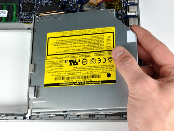
Lift the optical drive up and out of the computer.
-
-
이 단계는 번역되지 않았습니다. 번역을 도와주십시오
-
Disconnect the hard drive and ExpressCard connectors from the left side of the logic board.
-
-
이 단계는 번역되지 않았습니다. 번역을 도와주십시오
-
Disconnect the iSight and display data cables from the logic board by sliding them straight back out of their connectors, removing tape as necessary.
-
-
이 단계는 번역되지 않았습니다. 번역을 도와주십시오
-
Disconnect the eight indicated connectors by placing a spudger beneath the wired side of each one and lifting up.
-
-
이 단계는 번역되지 않았습니다. 번역을 도와주십시오
-
Remove the silver 9.5 mm T6 Torx screw securing the ground loop in the display data cable to the casing.
-
-
이 단계는 번역되지 않았습니다. 번역을 도와주십시오
-
Remove the single black 6 mm T6 Torx screw securing the upper portion of the logic board to the lower case.
-
-
이 단계는 번역되지 않았습니다. 번역을 도와주십시오
-
Peel up the orange Kapton tape securing the right thermal sensor cable to the logic board.
-
-
이 단계는 번역되지 않았습니다. 번역을 도와주십시오
-
Remove the following 15 screws:
-
One 4.4 mm black Phillips screw to the right of the ram slot.
-
Eight 4.7 mm silver T6 Torx screws securing the logic board to the lower case.
-
One 6.2 mm black T6 Torx screw on the right side of the left fan.
-
Five 9.4 mm silver T6 Torx screws securing the left and right fans.
-
-
이 단계는 번역되지 않았습니다. 번역을 도와주십시오
-
Hold the logic board down with one hand and use your other hand to lift the left fan up from its housing. There is a piece of black tape securing the left fan to the heat sink. Carefully peel this tape up from the heat sink as you lift the left fan up.
-
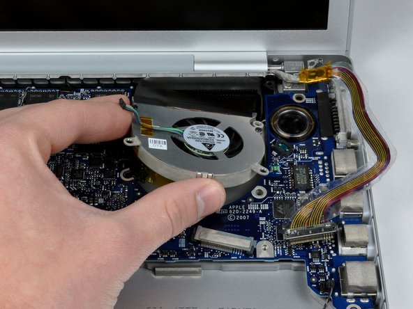
Lift the right fan up and carefully peel up the tape securing the fan to the heat sink as you go.
-
Remove the right fan from the computer.
-
-
이 단계는 번역되지 않았습니다. 번역을 도와주십시오
-
Lift up the left side of the logic board and disconnect the gray and black power cable from the bottom of the board.
-
Grasp the logic board at the left side and at the thin section, and rotate the logic board out of the lower case.
-
-
이 단계는 번역되지 않았습니다. 번역을 도와주십시오
-
Peel back the orange Kapton tape covering the middle thermal sensor.
-
Use a spudger to pry the middle thermal sensor off the heat sink.
-


다른 4명이 해당 안내서를 완성하였습니다.

댓글 2개
Do you happen to know if MacBook Pro thermal sensors are normally open (NO) or normally closed (NC)? I have a dead A1261 logic board, and one of the thermal sensor connectors came loose from its two wires when I was trying to carefully pry the connector out of its slot in preparation for sending out the logic board for repair or replacement. The connector is so tiny, you literally need a magnifying glass to see what you're doing and it's a challenge to pry it out without accidentally causing damage. Since I already have the dead logic board out of the case, I will replace the thermal sensor before putting a new or repaired logic board back in. I was just curious if a MacBook Pro will boot and run without the sensor connected to the logic board? Presumably this would cause the associated fan to either stay permanently off, or permanently on, depending on whether the sensor is NO or NC, right? Thank you.
Erik Maher - 답글