주요 콘텐츠로 건너뛰기

이 버전에는 잘못된 편집 사항이 있을 수 있습니다. 최신 확인된 스냅샷으로 전환하십시오.

필요한 것

  1. , 하단 케이스: 1 단계, 이미지 1/1
    • 하단 케이스를 상단 케이스에 고정하는 다음 나사 열 개를 풀어주세요:

    • 3mm Phillips/십자 나사 일곱 개

    • 13.5mm Phillips/십자 나사 세 개.

  2. : 2 단계, 이미지 1/1
    • 하단 케이스 벤트 근처를 두 손으로 들어올려 하단 케이스를 상단 케이스에 고정하는 클립 두 개를 분리하세요.

    • 하단 케이스를 분리하고 치워 놓으세요.

  3. , 배터리: 3 단계, 이미지 1/1
    이 단계에 사용된 도구:
    P6 Pentalobe Screwdriver 2009 15" MacBook Pro Battery
    $5.49
    구매
    • Pentalobe/펜타로브/별 나사 세 개가 배터리를 상단 케이스에 고정합니다. 이 특수 드라이버로 나사들을 풀수있습니다.

    • Pentalobe/펜타로브/별 나사 드라이버가 없는 경우, 유사시에는 1.5mm 일자 드라이버를 사용할 수 있습니다. 일자 드라이버의 머리가 나사 머리의 5 “점” 중 두 개에 꼭 맞도록 확인하세요. 헐거운 맞춤은 나사 머리를 쉽게 손상합니다.

    • 드라이버 헤드가 너무 헐거우면 계속 진행하기 전에 더 큰 비트를 찾아서 꼭 맞을 때까지 줄로 갈아 주세요.

    • 하드 드라이브를 교체하기 위해 3-7 단계를 따라서 배터리를 분리할 필요는 없습니다. 그러나 전자제품에 작업하기 전에 모든 전원을 분리하는 것을 권장합니다.

  4. : 4 단계, 이미지 1/1
    • 배터리 상단 가장자리에 노출된 5-점 Pentalobe/펜타로브/별 나사 두 개를 분리하세요.

  5. : 5 단계, 이미지 1/1
    • Spudger/스퍼저의 뾰족한 끝을 사용하여 "경고: 배터리를 분리하지 마시오" 스티커의 탭을 뒤로 구부리고 밑에 숨겨져 있는 5-점 Pentalobe/펜타로브/별 나사를 풀어주세요.

  6. : 6 단계, 이미지 1/2 : 6 단계, 이미지 2/2
    • 플라스틱 당김 탭으로 배터리를 들어 올리고 케이스 상단의 긴 가장자리에서 멀리 미세요.

    • 아직 배터리를 완전히 분리하지 마세요.

  7. : 7 단계, 이미지 1/1
    • 배터리 케이블 커넥터에 접근할 수 있도록 배터리를 뒤로 젖히세요.

    • 배터리 케이블 커넥터를 로직 보드 소켓에서 빼고 배터리를 상단 케이스에서 분리하세요.

    • 새 배터리를 설치하는 경우 설치 후 보정해야 합니다.

  8. 이 단계는 번역되지 않았습니다. 번역을 도와주십시오

    : 8 단계, 이미지 1/2 : 8 단계, 이미지 2/2
    • Apple sticks a small strip of clear plastic with adhesive applied to one side to the logic board behind the camera cable connector to keep it in its socket. When moving it out of the way, be sure not to break any surface-mount components off the logic board.

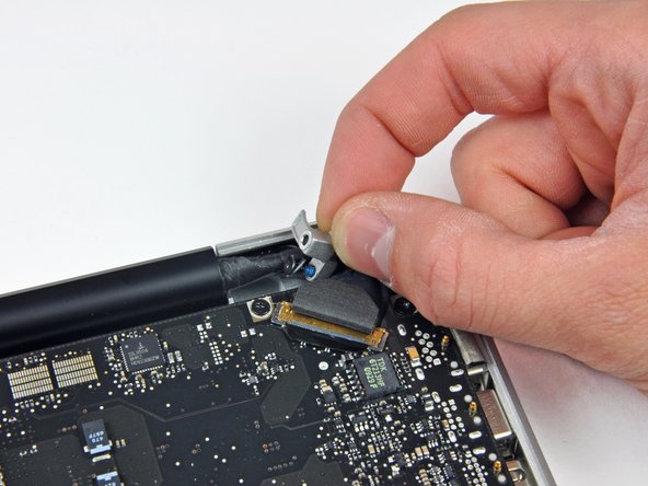
    • Hold the end of the cable retainer down with one finger while you use the tip of a spudger to slightly lift the other end and rotate it away from the camera cable connector.

    • Pull the camera cable away from its socket on the logic board.

    • Pull the connector parallel to the face of the logic board, not straight up.

  9. 이 단계는 번역되지 않았습니다. 번역을 도와주십시오

    : 9 단계, 이미지 1/1
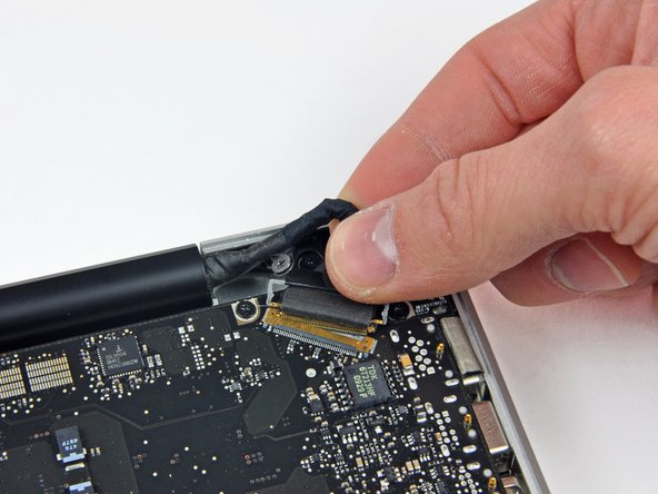
    • Peel the camera cable off the adhesive securing it to the optical drive.

  10. 이 단계는 번역되지 않았습니다. 번역을 도와주십시오

    : 10 단계, 이미지 1/2 : 10 단계, 이미지 2/2
    • This step is only required if you have an anti-glare display. If you have a glossy display, skip to step 12.

    • Disconnect the Bluetooth cable by pulling the male end straight away from its socket.

    • Pull the connector parallel to the face of the logic board, not straight up.

    • Use the flat end of a spudger to pry the Bluetooth antenna cable from its socket on the board.

  11. 이 단계는 번역되지 않았습니다. 번역을 도와주십시오

    : 11 단계, 이미지 1/2 : 11 단계, 이미지 2/2
    • This step is only required if you have an anti-glare display.

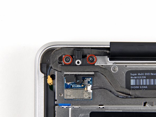
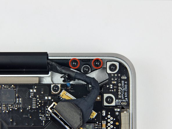
    • Remove the two 8 mm Phillips screws securing the Bluetooth/camera cable retainer to the upper case.

    • One of the screws may remain captive in the Bluetooth/camera cable ground loop. If replacing the display, be sure to transfer this screw to the new unit.

    • Lift the Bluetooth board/cable retainer assembly out of the upper case.

  12. 이 단계는 번역되지 않았습니다. 번역을 도와주십시오

    : 12 단계, 이미지 1/2 : 12 단계, 이미지 2/2
    • This step is only for glossy display machines. If you have an anti-glare display, skip this step.

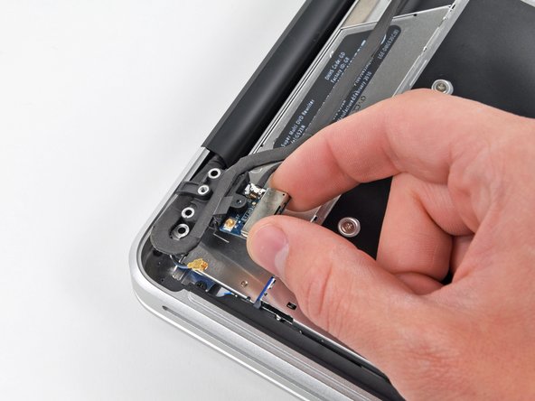
    • Remove the two 8 mm Phillips screws securing the camera cable retainer to the upper case.

    • One of the screws may remain captive in the camera cable ground loop. If replacing the display, be sure to transfer this screw to the new unit.

    • Lift the camera cable retainer out of the upper case.

  13. 이 단계는 번역되지 않았습니다. 번역을 도와주십시오

    : 13 단계, 이미지 1/2 : 13 단계, 이미지 2/2
    • Remove the single 7 mm Phillips screw securing the display data cable retainer to the upper case.

    • This screw may remain captive in the display data cable ground loop. If replacing the display, be sure to transfer this screw to the new unit.

    • Remove the display data cable retainer from the upper case.

  14. 이 단계는 번역되지 않았습니다. 번역을 도와주십시오

    : 14 단계, 이미지 1/2 : 14 단계, 이미지 2/2
    • Grab the plastic pull tab secured to the display data cable lock and rotate it toward the DC-in side of the computer.

    • Pull the display data cable connector straight away from its socket.

    • Make sure to pull the connector parallel to the face of the logic board, not straight up from its socket.

  15. 이 단계는 번역되지 않았습니다. 번역을 도와주십시오

    : 15 단계, 이미지 1/2 : 15 단계, 이미지 2/2
    • Remove the outer two T6 Torx screws securing both display hinges to the upper case (four screws total).

  16. 이 단계는 번역되지 않았습니다. 번역을 도와주십시오

    : 16 단계, 이미지 1/1
    • Open your MacBook so the display is perpendicular to the upper case.

    • Place your opened MacBook on a table as pictured.

    • While holding the display and upper case together with your left hand, remove the remaining 6.5 mm Torx screw from the lower display bracket.

  17. 이 단계는 번역되지 않았습니다. 번역을 도와주십시오

    : 17 단계, 이미지 1/1
    • Be sure to hold the display and upper case together with your left hand. Failure to do so may cause the freed display/upper case to fall, potentially damaging each component.

    • Remove the last remaining 6 mm T6 Torx screw securing the display to the upper case.

  18. 이 단계는 번역되지 않았습니다. 번역을 도와주십시오

    : 18 단계, 이미지 1/3 : 18 단계, 이미지 2/3 : 18 단계, 이미지 3/3
    • Grab the upper case with your right hand and rotate it slightly toward the top of the display so the upper display bracket clears the edge of the upper case.

    • Rotate the display slightly away from the upper case.

    • Lift the display up and away from the upper case, minding any brackets or cables that may get caught.

결승점

다른 27명이 해당 안내서를 완성하였습니다.

Walter Galan

694,707 평판

안내서 1,203개 작성하였습니다

댓글 3개

I was able to swap out the screen assembly for a 2009 MB Pro (2.8 GHz/4/500) using the screen from the 2009 MB Pro (2.53 GHz/4/250) within 30 minutes using this guide--extremely helpful and well done. Thank you!

Ram - 답글

Will a 2010 A1286 Display assembly fit a 2009 A1286 Macbook Pro?

Arne Büsing - 답글

I greatly appreciated your comment in Step 8 saying: “Apple sticks a small strip of clear plastic with adhesive applied to one side to the logic board behind the camera cable connector to keep it in its socket“.

My problem was that I had an old Macbook Pro whose camera cable was out of its socket and I could not get it in because this piece of plastic was in the way. I had no idea what it was. It was not clear to me if it was an IC or some other important component. Your comment clarified what it was and its purpose.

Pushing down on it at one end did not achieve anything, so I have just lifted it up and off the board using a small scalpel blade.

I will use some tape to hold the cable connector in its socket.

Thank you

Michael Walsh - 답글

댓글 쓰기

조회 통계:

24 시간 전: 4

7일 전: 7

30일 전: 29

전체 시간: 34,474