이 버전에는 잘못된 편집 사항이 있을 수 있습니다. 최신 확인된 스냅샷으로 전환하십시오.
필요한 것
-
이 단계는 번역되지 않았습니다. 번역을 도와주십시오
-
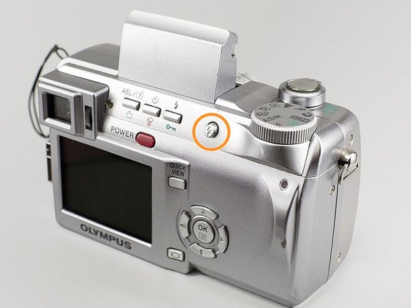
Use a Phillips #00 screwdriver to remove the single 4mm screw located directly to the right of the viewfinder on the back of the camera.
-
Remove the two 2mm screws from the left side panel.
-
Remove the single 3mm screw from the right side panel.
-
Remove the five 3mm screws from the bottom of the camera.
-
-
이 단계는 번역되지 않았습니다. 번역을 도와주십시오
-
Rock the two ribbon cables gently out of their sockets.
-
Grasp and pull the white cable out of its clip with metal tweezers.
-
Remove the back panel completely.
-
-
이 단계는 번역되지 않았습니다. 번역을 도와주십시오
-
Peel off the black plastic sheets.
-
Use the Phillips #00 screwdriver to remove the two 3mm screws holding the motherboard in place.
-
-
이 단계는 번역되지 않았습니다. 번역을 도와주십시오
-
Remove the ribbon cable directly below the viewfinder.
-
Detach the white plastic clip from its socket with a pair of tweezers.
-
Disconnect the ribbon cable from the center of the board, near the central hole.
-
Disconnect the three ribbon cables from the top right of the motherboard, near the selector wheel. One is on the top of the board, and the other two are on the underside.
-
-
-
이 단계는 번역되지 않았습니다. 번역을 도와주십시오
-
Remove the single 3mm ground screw attached to the right side of the camera body using the Phillips #00 screwdriver.
-
-
이 단계는 번역되지 않았습니다. 번역을 도와주십시오
-
Use the soldering iron to desolder the connections from the motherboard.
-
-
이 단계는 번역되지 않았습니다. 번역을 도와주십시오
-
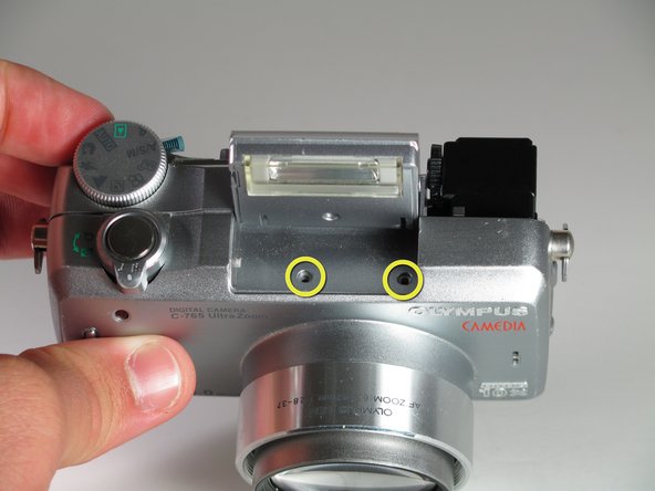
In order to access the flash assembly, you need to remove several interior components from the body of the camera.
-
With a Phillips #00 screwdriver, unscrew the two 3mm screws from the right side of the casing.
-
Raise the flash by pressing the shutter button or lifting the flash up with your fingers to access the two body screws underneath.
-
Using the Phillips #00 screwdriver, unscrew the two 3mm screws by twisting counterclockwise.
-
-
이 단계는 번역되지 않았습니다. 번역을 도와주십시오
-
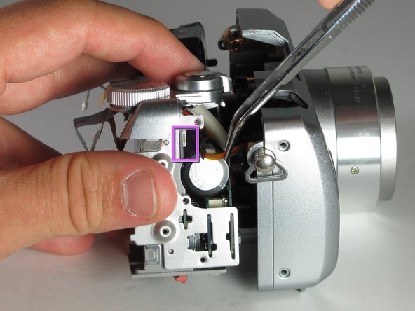
Gently pull the battery casing and the A/V ports away from the camera body to remove the connected components.
-
Using ESD Safe Blunt Nose Tweezers, gently remove the small ribbon cable from the right side of the casing
-
-
이 단계는 번역되지 않았습니다. 번역을 도와주십시오
-
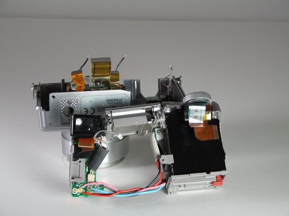
With a Phillips #00 screwdriver, unscrew the 3mm screw holding the flash assembly in place by twisting counter-clockwise.
-
Cut the wires running out from the flash assembly. When installing the new flash assembly, splice the new wires into the preexisting wires.
-
The camera is now ready for you to install a new flash assembly.
-


팀

Cal Poly, Team 12-33, Maness Spring 2011 Cal Poly, Team 12-33, Maness Spring 2011 회원
CPSU-MANESS-S11S12G33
3 회원들
안내서 7개 작성하였습니다