주요 콘텐츠로 건너뛰기
수리 커뮤니티 가입 - 계정 만들기

Retro-Bit Retro Duo Circuit Board Replacement

필요한 것

  1. Retro-Bit Retro Duo Circuit Board Replacement, Circuit Board: 1 단계, 이미지 3개 중 1개 Retro-Bit Retro Duo Circuit Board Replacement, Circuit Board: 1 단계, 이미지 3개 중 2개 Retro-Bit Retro Duo Circuit Board Replacement, Circuit Board: 1 단계, 이미지 3개 중 3개
    • With the console on its top, remove the four 12 mm Phillips #2 screws.

    • There may be a sticker covering one or more of the screws. Simply remove the sticker before screw removal.

    • Flip the console on its feet. Carefully lift the top casing from the back (where the AV/S and power ports are).

    • To avoid damage, do not remove the top casing completely. There is a small LED circuit board connected to the main circuit board.

    댓글 쓰기

  2. Retro-Bit Retro Duo Circuit Board Replacement: 2 단계, 이미지 3개 중 1개 Retro-Bit Retro Duo Circuit Board Replacement: 2 단계, 이미지 3개 중 2개 Retro-Bit Retro Duo Circuit Board Replacement: 2 단계, 이미지 3개 중 3개
    • Remove the one 6 mm Phillips #0 LED circuit board screw.

    • Lift the top case and set aside.

    댓글 쓰기

  3. Retro-Bit Retro Duo Circuit Board Replacement: 3 단계, 이미지 3개 중 1개 Retro-Bit Retro Duo Circuit Board Replacement: 3 단계, 이미지 3개 중 2개 Retro-Bit Retro Duo Circuit Board Replacement: 3 단계, 이미지 3개 중 3개
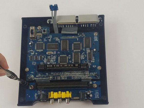
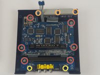
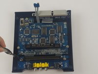
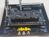
    • Remove the 11 screws holding the circuit boards and ports in place.

    • Six 11 mm Phillips #2 holding the circuit boards.

    • Three 12 mm Phillips #2 screws holding the controller ports.

    • Two 7 mm Philllips #2 screws holding the back ports

    댓글 쓰기

  4. Retro-Bit Retro Duo Circuit Board Replacement: 4 단계, 이미지 3개 중 1개 Retro-Bit Retro Duo Circuit Board Replacement: 4 단계, 이미지 3개 중 2개 Retro-Bit Retro Duo Circuit Board Replacement: 4 단계, 이미지 3개 중 3개
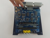
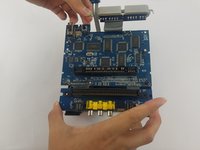
    • Carefully lift the circuit board while holding either the AV or controller ports. Alternatively, you can hold the circuit board on its edges.

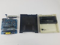
    • Make sure to lift the circuit board completely out of the bottom case.

    • To avoid damage, do not to touch the top or bottom faces of the circuit board.

    댓글 쓰기

결론

To reassemble your device, follow these instructions in reverse order.
취소: 해당 안내서를 완성하지 않았습니다.

작성자

3다른 기여자 명과 함께

Truong Vo

회원 가입일: 09/25/17

324 평판

안내서 3개를 작성함

USF Tampa, Team S4-G4, Eyestone Fall 2017 USF Tampa, Team S4-G4, Eyestone Fall 2017 회원

USFT-EYESTONE-F17S4G4

3 회원들

안내서 10개를 작성함

1가이드 댓글

I hope you show the second part were you replace the 72pin connector. Please include part source.

The 72 pin connector grabs too tightly on the cart.

Thanks.

George Tedrick - 답글 공유

댓글 쓰기

조회 통계:

지난 24시간: 1

지난 7일: 9

지난 30일: 51

전체 시간: 3,219