소개
You will need knowledge of how to use a soldering iron. For more information regarding soldering visit: Soldering Skills
Used for mother board replacement and repair If the unit starts behaving erratically. Along the process you will determine if the behavior is not due to a faulty power jack, wires, and or microphone. If so proceed with motherboard replacement.
필요한 것
-
-
-
Along the back of unit there are two 4mm philips head screws towards the bottom of the unit. Start by removing these two screws using your PH0 screwdriver.
 FixBot에 문의하기
-
-
-
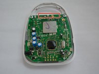
Using the plastic spudger gently pry along the middle of the 2 sections of the plastic housing in order to release plastic latches on the inside of the housing.
-
-
-
-
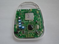
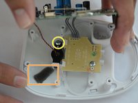
Remove the strip of adhesive tape located under the motherboard.
-
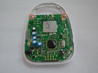
Gently lift the motherboard to expose the inner components.
-
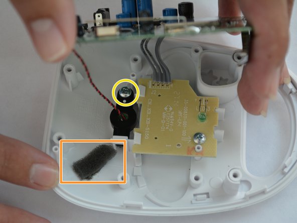
Use a spudger to scrape away the adhesive and foam connecting the microphone.
-
Unscrew the 4mm phillips head screw holding the microphone in place.
-
-
이 단계에 사용된 도구:Desoldering Pump$3.99
-
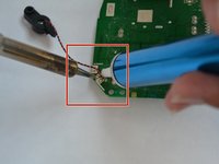
De-solder the connections from the motherboard using a soldering iron and a solder sucker.
-
De-solder the connections to the microphone, located on the bottom left of the mother board.
-
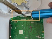
De-solder the 4 wires connecting the LED board to the motherboard.
-
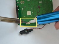
De-solder the antenna's solder joint, located above the microphone wire connection.
-
-


To reassemble your device, follow these instructions in reverse order.
팀

USF Tampa, Team 6-3, Remmell Fall 2015 USF Tampa, Team 6-3, Remmell Fall 2015 회원
USFT-REMMELL-F15S6G3
4 회원들
안내서 7개를 작성함