필요한 것
-
-
Remove the four T5 screws.
-
Remove the single T5 screw from the bottom, next to the charging port.
-
-
-
Remove the screws from the sides.
-
Remove the screws holding the camera frame.
Press the chamfered left or right extremities of the frame (between the screws) to rock the frame loose. The opposite side will pop-up, to lift off easily.
-
-
-
Pry out the sim car holder
-
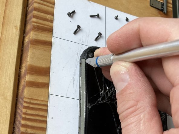
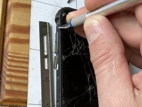
Use a spudger or a utility knife to pry off the side bezels.
-
-
-
-
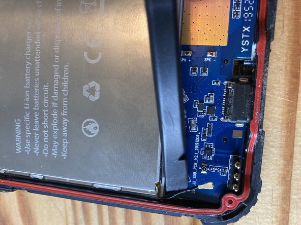
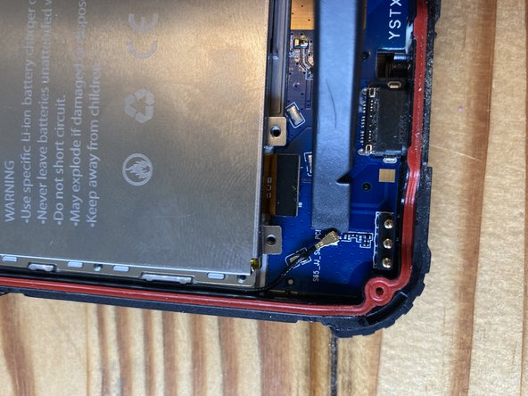
Use a plastic spudger to disconnect the flex connector and the antenna
-
-
이 단계에 사용된 도구:Tweezers$4.99
-
Heat up this PCB with either iOpener or a heat gun on low temp (100-120 Celsius) to loosen the adhesive and pry it off from the side.
-
Remove the screws.
-
The last screw is under a tamper-proof sticker
-
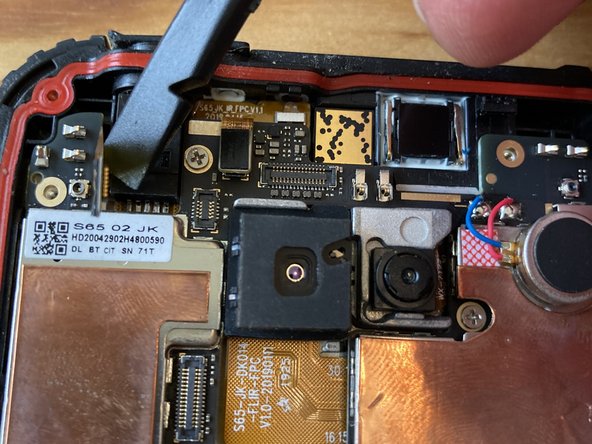
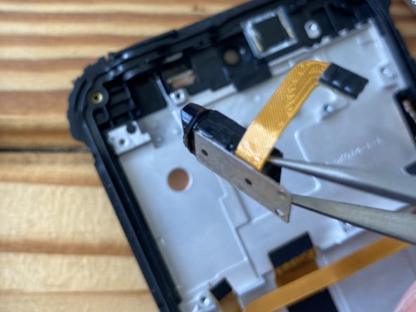
Use plastic spudger or tweezers to disconnect the camera flex cable from the top
-
Disconnect the flex cable
-
Disconnect the antenna
-
-
-
Remove two J000 screws
-
Carefully pry up the camera. Heat from the glass side if necessary.
-
Unscrew and remove the camera assembly
-
-
-
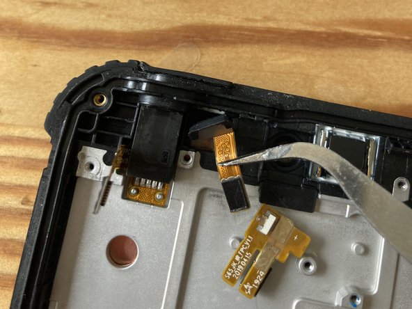
Heat the light sensor from both sides to loosen the adhesive and gently pry them out of their sockets
-
-
-
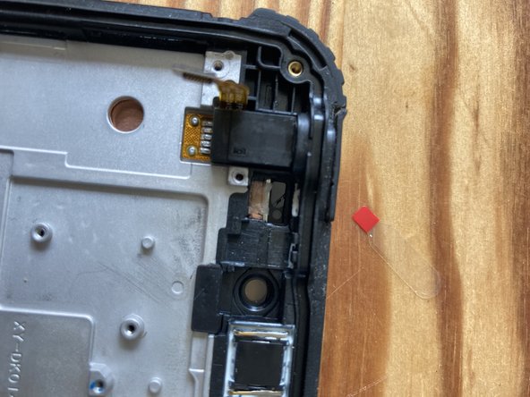
Use some isopropyl alcohol if necessary to loosen the glue further on the audio jack
-
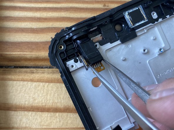
Grab it with strong tweezers and wiggle from side to side and upwards until it comes out. Heat further if necessary.
-
Lift it out and transfer to the new screen.
-
-
-
Gently peel the flex cable u p and transfer to the new assembly.
-
Heat up and pry up the bottom PCB (charging port) and transfer to the new screen.
-


To reassemble your device, follow these instructions in reverse order.
To reassemble your device, follow these instructions in reverse order.
다른 6명이 해당 안내서를 완성하였습니다.

Might want to add importance of magnetic something to keep screws organized. Amazing how many people don't pay attention to the concept of putting screws back into same hole they came out of
Shelly J Webb - 답글