
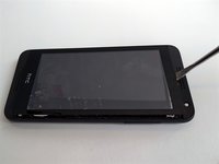
HTC Desire 610 Glass Screen Replacement
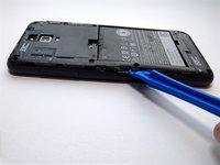
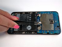
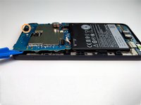
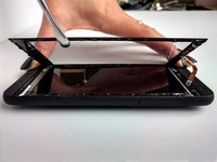
You will need to purchase a new screen to replace the old one. In one of the final steps of this guide, you will need to remove the glass screen on the front of the phone. To do this, we used a metal spudger.
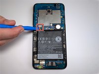
Remember: when working with electronics, it's important to choose a tool that's ESD-safe to avoid accidental damage to the device. The metal spudger is great when you need serious prying power, but the regular black nylon spudger or a plastic opening tool should be used whenever possible.


To reassemble your device, follow these instructions in reverse order.
To reassemble your device, follow these instructions in reverse order.
다른 9명이 해당 안내서를 완성하였습니다.
팀

University of Alabama, Team 1-2, Sydow campbell Spring 2016 University of Alabama, Team 1-2, Sydow campbell Spring 2016 회원
UA-SYDOW CAMPBELL-S16S1G2
4 회원들
안내서 6개를 작성함
댓글 6개
hey i followed directions flawlessly and for some reason, now the new lcd wont show the display...i get a flash of a grey-whitish screen when it powers on then its black. i can hear the sound and everything, just now display at the moment, everything is connected correctly and i went took the phone apart again just to make sure and it seems like i did everything right so im at a loss right now. any advice or tips?
Same here. Before touchscreen replacement the screen was showing but was not touch responsive. Now after touch screen replacement completely black.
I wonder if that has something to do with how screen connects to motherboard. If we removed the cable connecting touchscreen, where was the display cable then? How is it connected to motherboard? Through touchscreen?
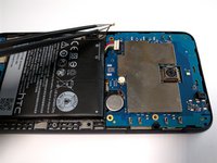
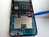
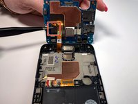
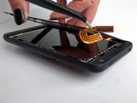
Hi Guys, I also had the above issue however. you'll notice on step 10 (second picture) there is a ribbon cable that needs connecting to the board at the battery end, it runs underneath the battery. I could not do this with the battery in place so had to lift it out using a spudger. Once the battery is out you'll probably find it easier to connect this bottom cable first and then attach the digitizer ribbon. I did this with the phone on it's side. It's a touch fiddly but it can be done.
I hope that helps
That was it. Thanks
Zach -
Had the same issue with the ribbon cable under the battery. Needs to be fully inserted and just can't be easily connected when replacing the logic board. Removing the battery from the right side, but leaving it attached on the left made connecting the ribbon cable easier.