주요 콘텐츠로 건너뛰기

이 버전에는 잘못된 편집 사항이 있을 수 있습니다. 최신 확인된 스냅샷으로 전환하십시오.

필요한 것

  1. , 하단 케이스: 1 단계, 이미지 1/1
    • 하단 케이스를 상단 케이스에 고정하는 다음 나사 열 개를 풀어주세요:

    • 3mm Phillips/십자 나사 일곱 개

    • 13.5mm Phillips/십자 나사 세 개

  2. : 2 단계, 이미지 1/2 : 2 단계, 이미지 2/2
    • 하단 케이스 벤트 근처를 두 손으로 들어올려 하단 케이스를 상단 케이스에 고정하는 클립 두 개를 분리하세요.

    • 하단 케이스를 분리하고 치워 놓으세요.

  3. , 배터리: 3 단계, 이미지 1/1
    이 단계에 사용된 도구:
    P6 Pentalobe Screwdriver 2009 15" MacBook Pro Battery
    $5.49
    구매
    • 배터리 상단 가장자리에서 5-점 Pentalobe/펜타로브/별 나사 두 개를 분리하세요.

    • 하드 드라이브를 교체하기 위해 3-6 단계를 따라서 배터리를 분리할 필요는 없습니다. 그러나 전자제품에 작업하기 전에 모든 전원을 분리하는 것을 권장합니다.

  4. : 4 단계, 이미지 1/1
    • Spudger/스퍼저의 뾰족한 끝을 사용하여 "경고: 배터리를 분리하지 마시오" 스티커의 탭을 뒤로 구부리고 밑에 숨겨져 있는 세 번째 5-점 Pentalobe/펜타로브/별 나사를 풀어주세요.

  5. : 5 단계, 이미지 1/2 : 5 단계, 이미지 2/2
    • 플라스틱 당김 탭으로 배터리를 들어 올리고 케이스 상단의 긴 가장자리에서 멀리 미세요.

    • 아직 배터리를 완전히 분리하지 마세요.

  6. : 6 단계, 이미지 1/1
    • 배터리 케이블 커넥터에 접근할 수 있도록 배터리를 뒤로 젖히세요.

    • 배터리 케이블 커넥터를 로직 보드 소켓에서 빼고 배터리를 상단 케이스에서 분리하세요.

    • 새 배터리를 설치하는 경우 설치 후 보정해야 합니다.

  7. 이 단계는 번역되지 않았습니다. 번역을 도와주십시오

    : 7 단계, 이미지 1/3 : 7 단계, 이미지 2/3 : 7 단계, 이미지 3/3
    • Use a spudger to pry the fan connector straight up off the logic board.

    • It is useful to twist the spudger axially from beneath the fan cable wires to release the connector.

    • The fan socket and the fan connector can be seen in the second and third pictures. Be careful not to break the plastic fan socket off the logic board as you use your spudger to lift the fan connector straight up and out of its socket. The layout of the logic board shown in the second picture may look slightly different than your machine but the fan socket is the same.

  8. 이 단계는 번역되지 않았습니다. 번역을 도와주십시오

    : 8 단계, 이미지 1/2 : 8 단계, 이미지 2/2
    • Remove the three T6 Torx screws securing the left fan to the logic board.

    • Lift the fan out of the upper case.

  9. 이 단계는 번역되지 않았습니다. 번역을 도와주십시오

    : 9 단계, 이미지 1/1
    • Use the flat end of a spudger to disconnect the left fan connector from the logic board.

    • Pry up from beneath the wires.

  10. 이 단계는 번역되지 않았습니다. 번역을 도와주십시오

    : 10 단계, 이미지 1/2 : 10 단계, 이미지 2/2
    • Remove the three T6 Torx screws securing the left fan to the logic board.

    • Lift the left fan out of the upper case.

  11. 이 단계는 번역되지 않았습니다. 번역을 도와주십시오

    : 11 단계, 이미지 1/1
    • The camera cable connector is not secured by any locking or snapping mechanism. Hence, Apple sticks a small strip of black plastic with adhesive applied to the side facing the logic board behind the camera cable connector to keep it in its socket.

    • When moving the strip (cable retainer) out of the way, be sure not to break any surface-mounted components off the logic board.

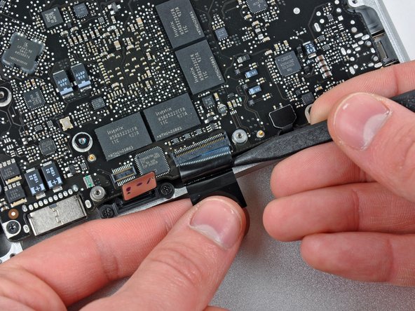
    • Hold the end of the cable retainer down with one finger while you use the tip of a spudger to slightly lift the other end and rotate it away from the camera cable connector.

    • Disconnect the camera cable by pulling the male end straight away from its socket.

    • Pull the connector parallel to the face of the logic board, not straight up.

  12. 이 단계는 번역되지 않았습니다. 번역을 도와주십시오

    : 12 단계, 이미지 1/1
    • Disconnect the camera cable by pulling the male end straight away from its socket.

    • Pull the connector parallel to the face of the logic board, not straight up.

  13. 이 단계는 번역되지 않았습니다. 번역을 도와주십시오

    : 13 단계, 이미지 1/1
    • Use the flat end of a spudger to pry the optical drive cable connector up off the logic board.

  14. 이 단계는 번역되지 않았습니다. 번역을 도와주십시오

    : 14 단계, 이미지 1/1
    • Using the flat end of a spudger, pry the subwoofer connector straight up from the connector jack.

    • Be careful to pry the connector, not the socket. It's possible to accidentally pry the socket up from the logic board.

    • Removing the foam applied to the top of the connector will make it easier to see and avoid prying up the socket.

  15. 이 단계는 번역되지 않았습니다. 번역을 도와주십시오

    : 15 단계, 이미지 1/1
    • Use the flat end of a spudger to pry the hard drive/IR sensor cable connector up off the logic board.

  16. 이 단계는 번역되지 않았습니다. 번역을 도와주십시오

    : 16 단계, 이미지 1/2 : 16 단계, 이미지 2/2
    • Remove the two 1.5 mm Phillips screws securing the cable cover to the logic board.

    • Lift the cable cover out of the upper case.

  17. 이 단계는 번역되지 않았습니다. 번역을 도와주십시오

    : 17 단계, 이미지 1/1
    • Use a spudger to pry the trackpad flex ribbon cable connector up off the logic board.

  18. 이 단계는 번역되지 않았습니다. 번역을 도와주십시오

    : 18 단계, 이미지 1/2 : 18 단계, 이미지 2/2
    • Use your fingernail to flip up the locking flap on the ZIF socket for the keyboard ribbon cable. The locking flap is located at the opposite side of the socket compared to the keyboard ribbon cable. Hook your fingernail under it and carefully lift it up vertically.

    • Do not attempt to slide the keyboard ribbon cable out of its socket before you have unlocked the ZIF socket. Ribbon cables are fragile and excessive force will easily break them.

    • Use the tip of a spudger to slide the keyboard ribbon cable out of its socket.

  19. 이 단계는 번역되지 않았습니다. 번역을 도와주십시오

    : 19 단계, 이미지 1/1
    • Use a spudger to pry the battery indicator ribbon cable connector up off the logic board.

  20. 이 단계는 번역되지 않았습니다. 번역을 도와주십시오

    : 20 단계, 이미지 1/2 : 20 단계, 이미지 2/2
    • Remove the single 7 mm Phillips screw securing the display data cable retainer to the upper case.

    • This screw may remain captive in the display data cable ground loop. If replacing the display, be sure to transfer this screw to the new unit.

    • Remove the display data cable retainer from the upper case.

  21. 이 단계는 번역되지 않았습니다. 번역을 도와주십시오

    : 21 단계, 이미지 1/2 : 21 단계, 이미지 2/2
    • Grab the plastic pull tab secured to the display data cable lock and rotate it toward the DC-in side of the computer.

  22. 이 단계는 번역되지 않았습니다. 번역을 도와주십시오

    : 22 단계, 이미지 1/1
    • Pull the display data cable connector straight away from its socket.

    • Make sure to pull the connector parallel to the face of the logic board, not straight up from its socket.

  23. 이 단계는 번역되지 않았습니다. 번역을 도와주십시오

    : 23 단계, 이미지 1/2 : 23 단계, 이미지 2/2
    • Using the tip of a spudger, flip up the keyboard backlight ribbon cable retaining flap.

    • Pull the keyboard backlight ribbon cable straight out of its socket.

  24. 이 단계는 번역되지 않았습니다. 번역을 도와주십시오

    : 24 단계, 이미지 1/1
    • Remove the following screws:

    • Seven 3.3 mm T6 Torx screws securing the logic board to the upper case.

    • Two 8 mm T6 Torx screws securing the DC-In board to the upper case.

    • Do not remove the logic board yet! There are components on the underside of the logic board attached to the the upper case that must first be disconnected.

  25. 이 단계는 번역되지 않았습니다. 번역을 도와주십시오

    : 25 단계, 이미지 1/1
    • Carefully lift the logic board assembly from the left side and work it out of the upper case, minding the port side that may get caught during removal.

    • Do not entirely remove the logic board yet!

  26. 이 단계는 번역되지 않았습니다. 번역을 도와주십시오

    : 26 단계, 이미지 1/1
    • Lift the logic board enough to gain clearance and use a spudger to pry the microphone up off the upper case.

    • Slide the logic board away from the port openings and lift the assembly out of the upper case.

    • Before reinstalling the logic board, it is easiest to press the microphone down into its housing in the left speaker to keep it in place.

  27. 이 단계는 번역되지 않았습니다. 번역을 도와주십시오

    : 27 단계, 이미지 1/1
    • Slide the logic board away from the port openings and lift the assembly out of the upper case.

    • Before reinstalling the logic board, it is easiest to press the microphone down into its housing in the left speaker to keep it in place.

  28. 이 단계는 번역되지 않았습니다. 번역을 도와주십시오

    : 28 단계, 이미지 1/1
    • If your microphone is still inserted into its void in the left speaker housing, use the tip of a spudger to lift it out.

  29. 이 단계는 번역되지 않았습니다. 번역을 도와주십시오

    : 29 단계, 이미지 1/1
    • Remove the small strip of tape covering the left speaker connector.

  30. 이 단계는 번역되지 않았습니다. 번역을 도와주십시오

    : 30 단계, 이미지 1/1
    • Use the flat end of a spudger to pry the left speaker connector up off its socket on the logic board.

    • Pry up from beneath the wires.

  31. 이 단계는 번역되지 않았습니다. 번역을 도와주십시오

    : 31 단계, 이미지 1/2 : 31 단계, 이미지 2/2
    • Remove the two 5 mm Phillips screws securing the left speaker to the logic board.

    • Lift the left speaker off the logic board.

  32. 이 단계는 번역되지 않았습니다. 번역을 도와주십시오

    : 32 단계, 이미지 1/1
    • Use the flat end of a spudger to pry the microphone cable connector up off its socket on the logic board.

    • Pry up from beneath the wires.

  33. 이 단계는 번역되지 않았습니다. 번역을 도와주십시오

    : 33 단계, 이미지 1/1
    • Disconnect the DC-In Board connector from the logic board by pulling it straight away from its socket.

  34. 이 단계는 번역되지 않았습니다. 번역을 도와주십시오

    : 34 단계, 이미지 1/1
    • Remove the eight Phillips screws securing the heat sink to the logic board.

    • Keep track of the springs under each of the screws as you remove them.

    • Do not press down on the screws excessively while breaking them free.

  35. 이 단계는 번역되지 않았습니다. 번역을 도와주십시오

    : 35 단계, 이미지 1/1
    • Carefully lift the heat sink off the logic board.

    • If the heat sink appears to be stuck to the logic board after removing all eight screws, it may be helpful to use a spudger to separate the two components.

    • When reinstalling your logic board, don't forget to apply a new layer of thermal paste to the face of each processor.

  36. 이 단계는 번역되지 않았습니다. 번역을 도와주십시오

    : 36 단계, 이미지 1/2 : 36 단계, 이미지 2/2
    • Release the tabs on each side of the RAM chip by simultaneously pushing each tab away from the chip.

    • These tabs lock the chip in place and releasing them will cause the chip to "pop" up.

    • After the RAM chip has popped up, pull it straight out of its socket.

    • Repeat this process if a second RAM chip is installed.

결승점

다른 39명이 해당 안내서를 완성하였습니다.

Andrew Bookholt

586,399 평판

안내서 619개 작성하였습니다

댓글 한 개

Do NOT pull the subwoofer cable up. It pulls out — to the side. These instructions just ruined the motherboard as the weak subwoofer connector pulled off the motherboard, when it should have been pulled out to the side. Thanks a lot. Several hundred down the drain.

John - 답글

댓글 쓰기

조회 통계:

24 시간 전: 2

7일 전: 10

30일 전: 48

전체 시간: 77,951