소개
Use this guide to replace the joystick control modules on your Nintendo Switch Controller. To complete this project, you must be able to solder. Care should be taken in the removal of the plastic body pieces and the internal circuit board of the device to avoid damage that could render the device inoperable. This project also involves the removal of a lithium-ion battery, and if swollen, be sure to take appropriate precautions.
필요한 것
-
-
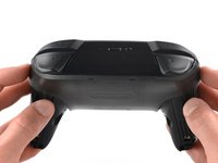
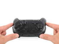
Flip the controller over so the model stickers face the ceiling.
-
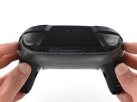
Use a JIS #00 screwdriver to remove the two black 8.4 mm screws that secure the handles, located at the ends of the handles.
 FixBot에 문의하기
-
-
-
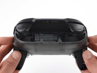
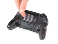
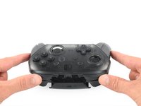
Carefully remove the handle covers by pulling them away from the main body.
-
-
-
Use a JIS #00 screwdriver to remove the four silver 6.8 mm screws that secure the clear back plastic cover.
-
-
-
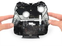
Carefully pry away the clear plastic cover using your fingernail.
-
-
-
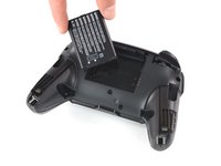
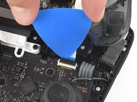
Remove the lithium-ion battery by using a fingernail or plastic opening tool to pry it up on the left side.
-
-
-
-
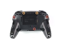
Use a Phillips #1 screwdriver to remove the five 5 mm screws from the back of the controller.
-
The two case screws above the handgrips and the single case screw below the battery bay have a shallow seat. These three screws can be easily removed.
-
The two case screws adjacent to the ZR and ZL shoulder buttons have a deep seat. Use an extension or a narrow PH1 Phillips screwdriver with a longer shaft to reach these screws.
-
-
-
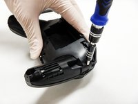
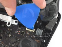
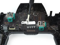
Use the tip of an opening pick to open the black flap of the ZIF connector by pushing it upwards.
-
-
이 단계에 사용된 도구:Tweezers$4.99
-
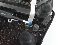
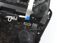
Use your fingers or a pair of blunt nose tweezers to disconnect the interconnect cable from its connector.
-
-
-
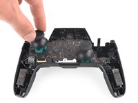
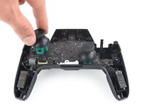
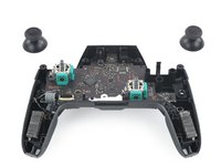
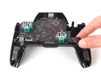
With light force pull the two joystick caps off of the controller.
-
-
-
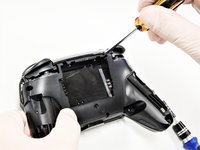
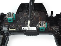
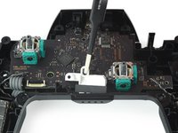
Use a PH1 Philipps screwdriver to remove the four 5 mm-long screws securing the motherboard.
-
-
이 단계에 사용된 도구:Tweezers$4.99
-
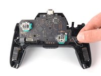
Use your fingernail or a pair of tweezers to pry the LED light away from its slot.
-
-
-
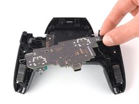
Loosen the circuit board off the chassis by gently pulling at the bottom right corner.
-
Lift the circuit board up to expose its backside.
-
-
이 단계에 사용된 도구:FixHub Smart Soldering Iron$79.95
-
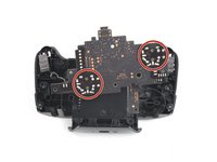
Turn to the backside of the circuit board for clear access to the solder joints.
-
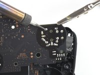
Desolder all of the outlined solder joints.
-
Remove the joystick module from the circuit board.
-


To reassemble your device, follow these instructions in reverse order.
다른 55명이 해당 안내서를 완성하였습니다.

팀

Cal Poly, Team S11-G2, Regan Fall 2019 Cal Poly, Team S11-G2, Regan Fall 2019 회원
CPSU-REGAN-F19S11G2
5 회원들
안내서 45개를 작성함
28가이드 댓글
I managed to replace mine with much difficulty with the soldering but the stick does not seem to turn fully anymore, both with the replacement and the original. For reference, when I go to test it, it no longer registers as reaching the outer circle when pressed all the way down. Similarly when I go to calibrate it, it only reaches up til about the 2nd outer circle, not enough to actually trigger the green arrow. Since this seems to occur on both the replacement and original stick now, I’m guessing this must be some issue that arose while I was struggling with the desoldering process. Anybody have any ideas what might be causing my issue? Have I just damaged it beyond repair?
Without pictures it is impossible to tell, but there is the possibility that you strips the metal connection on the solder point. This is fixable by “bridging” the connection. You will want to find schematics of the wiring for the PCB and then solder the wire over to the next connection.
As a side note, I should mention that I have never tried this on a controller of any sort and that I have only used this method on keyboards with single wire connections. It is possible that the connection in a controller PCB have more going on and that this technique will not work.
I have the same problem, I buy 2 joystick module from iFixit and the two gave me the same issue, the joystick module don't reach the green arrow.
I can't calibrate because of that issue.
Any ideas?
Piero Grasso - 답글 공유
I have also had the same issue with replacement, only reaches roughly 75%. I contacted ifixit and they sent me a replacement thinking it might be a faulty pot, I installed the new stick and have the same issue. Maybe different years used different resistance.
See my answer a bit down. I think it has to do with the resistance of the module. I had the same issue with the part I received from iFixit, the original part has a resistance of 1150 ohm, but the replacement is 1600 ohm. And I have a different module which is about 500 ohm, and that works just fine.