
Samsung Galaxy S23 Ultra Screen and Battery Assembly Replacement

Follow this guide to replace the screen and battery assembly on your Samsung Galaxy S23 Ultra.
This guide is written for the screen and battery assembly. The assembly consists of the screen, battery, and frame together in one part. Be sure you have the right part before you begin the repair.
Note: Retaining water resistance after the repair will depend on how well you reapply the adhesive, but your device will lose its IP (Ingress Protection) rating.
필요한 것
수리 키트
이 키트는 이 안내서를 완료하는데 필요한 모든 부품과 도구를 포함하고 있습니다.


부품


도구


더보기...
-
-
Heat an iOpener and apply it to the right edge of the back cover for two minutes.
-
-
-
While you wait for the adhesive to soften, note the following:
-
There's adhesive securing the back cover around the perimeter of the frame.
-
-
-
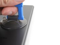
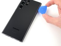
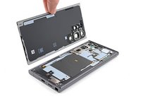
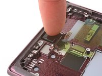
Apply a suction handle to the back cover, as close to the center of the right edge as possible.
-
Pull up on the suction handle with strong, steady force to create a gap between the cover and the frame.
-
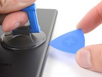
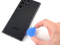
Insert an opening pick into the gap.
-
-
-
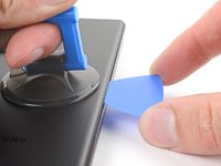
Slide the pick back and forth along the right edge to separate the adhesive.
-
Leave the pick inserted near the bottom right corner to prevent the adhesive from resealing.
-
-
-
Apply a heated iOpener to the bottom edge of the back cover for two minutes.
-
-
-
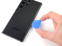
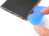
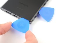
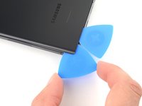
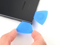
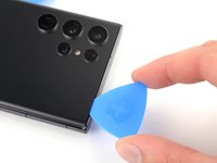
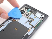
Insert a second opening pick at the bottom right corner.
-
Angle the pick upward to match the curved edge and rotate it around the bottom right corner.
-
-
-
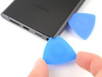
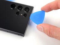
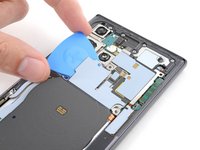
Slide your opening pick to the bottom left corner to separate the adhesive.
-
Leave the pick in the bottom left corner to prevent the adhesive from resealing.
-
-
-
Apply a heated iOpener to the left edge of the back cover for two minutes.
-
-
-
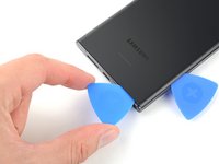
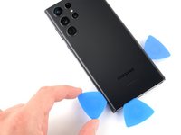
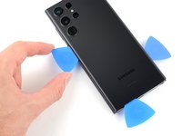
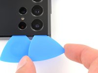
Insert a third opening pick at the bottom left corner.
-
Angle the pick upward to match the curved edge and rotate it around the bottom left corner.
-
-
-
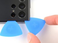
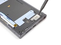
Slide your opening pick along the left edge to separate the adhesive, stopping when you reach the power button.
-
Leave the pick in the left edge to prevent the adhesive from resealing.
-
-
-
Heat an iOpener and apply it to the top edge of the back cover for two minutes.
-
-
-
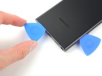
Insert an opening pick in the gap at the top right edge.
-
Angle the pick upward to match the curved edge and rotate it around the top right corner.
-
-
-
Slide the pick to the top left corner to separate the adhesive.
-
Leave the pick in to prevent the adhesive from resealing.
-
-
-
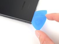
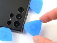
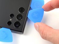
Insert an opening pick in the gap at the top left edge.
-
Angle the pick upward to match the curved edge and rotate it around the top left corner.
-
-
-
Slide the pick toward the bottom camera to separate through the remaining adhesive, stopping before you reach the power button.
-
-
-
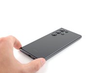
Grab and remove the back cover.
-
Remove any adhesive chunks with a pair of tweezers or your fingers. Apply heat if you're having trouble separating the adhesive.
-
If you're using custom-cut adhesives, follow this guide.
-
If you're using double-sided tape, follow this guide.
-
-
-
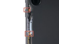
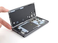
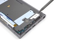
Use the pointed end of a spudger to pry up and disconnect the NFC antenna press connector from the motherboard.
-
Repeat for the wireless charging coil press connector.
-
-
-
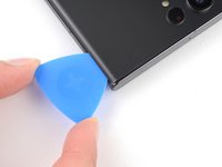
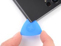
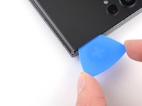
Insert an opening pick between the right edge of the wireless charging coil and the battery.
-
Slide the pick along the right edge to separate the adhesive.
-
-
-
-
Use a Phillips screwdriver to remove the five 3.5 mm-long screws securing the NFC antenna and charging coil.
-
-
-
Use a Phillips screwdriver to remove the six 3.5 mm screws securing the loudspeaker.
-
-
-
Insert the pointed end of your spudger between the upper right corner of the loudspeaker and the frame.
-
Pry up to unclip the loudspeaker from the frame.
-
-
-
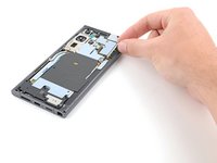
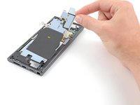
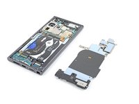
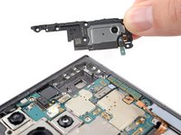
Grab and remove the NFC, wireless charging coil, and loudspeaker from the frame.
-
-
-
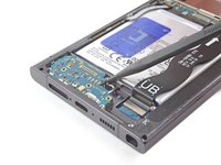
Use your spudger to pry up and disconnect the battery press connector.
-
-
-
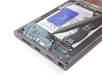
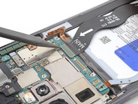
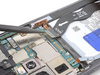
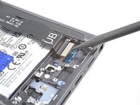
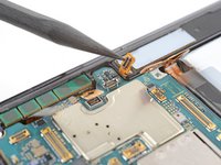
Use your spudger to pry up and disconnect the secondary interconnect cable press connector from the motherboard.
-
Repeat for the primary interconnect cable.
-
-
-
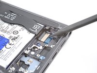
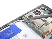
Use a Phillips screwdriver to remove the three 3.5 mm-long screws securing the charging board.
-
-
-
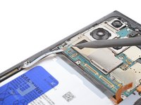
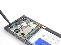
Insert the point of your spudger under the top right of the charging board.
-
Pry the charging board up from its recess until you can grab it with your fingers.
-
Pull the charging board toward the top of the device to remove it from its recess.
-
-
-
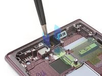
Use the point of your spudger to pry up and disconnect the earpiece speaker press connector.
-
-
-
Use a Phillips screwdriver to remove the five 3.5 mm-long screws securing the motherboard cover.
-
-
-
Insert the point of your spudger between the bottom right corner of the motherboard cover and the frame.
-
Pry up on the cover to unclip it from the frame.
-
Remove the motherboard cover.
-
-
-
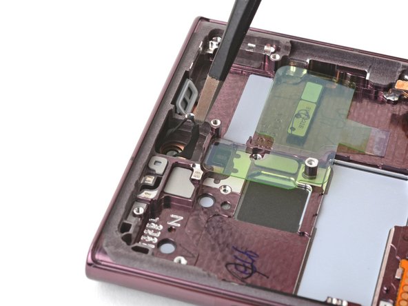
Use the point of your spudger to pry up and disconnect the front-facing camera press connector.
-
-
-
Use your spudger to pry up and disconnect the fingerprint reader press connector.
-
-
-
Use the point of your spudger to pry up and disconnect the screen press connector from the motherboard.
-
-
-
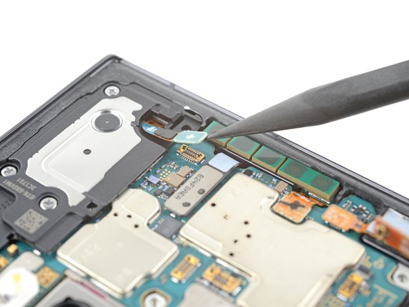
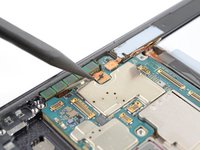
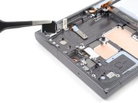
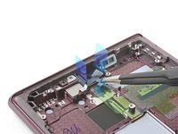
Use the point of your spudger to pry up and disconnect the right 5G mmWave antenna press connector.
-
-
-
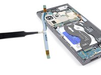
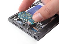
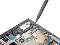
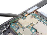
Use the point of your spudger to pry up and disconnect the stylus press connector.
-
-
-
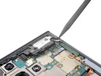
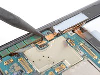
Use the point of your spudger to pry up and disconnect the left 5G mmWave antenna press connector.
-
-
-
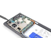
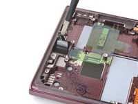
Use your Phillips screwdriver to remove the single 4 mm-long screw securing the motherboard.
-
-
-
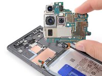
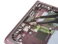
Insert the point of your spudger between the top left of the motherboard and the frame.
-
Pry the motherboard up until you can grab it with your fingers.
-
Grab the motherboard and remove it from the frame.
-
-
-
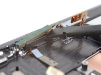
Heat an iOpener and apply it to the top of the screen for two minutes.
-
-
-
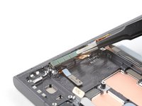
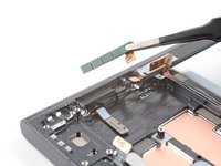
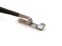
Use the flat end of your spudger to pry the front-facing camera from its recess.
-
-
-
Remove the black adhesive liner from the front-facing camera recess.
-
Peel and remove the foam liner from the new frame.
-
-
-
Remove the two large clear rectangular liners from the adhesive sheet and place the adhesives on the sides of the camera recess.
-
Remove the liner from the main adhesive piece and place it in the center of the camera recess with its pull tab facing the bottom of the frame.
-
Remove any adhesive residue from the front-facing camera module.
-
Remove the liner from the thin piece of adhesive and place it on the top edge of the camera.
-
-
-
Remove all four blue adhesive liners from the camera and the frame.
-
Insert the front-facing camera into its recess in the frame and apply pressure to secure it.
-
-
-
Use a Phillips driver to remove the two 2.4 mm‑long screws securing the left 5G mmWave antenna.
-
-
-
Grab the left 5G mmWave antenna connector and lift up to separate the bracket from the frame.
-
Remove the antenna.
-
-
-
Remove the antenna and connector from the old bracket.
-
Remove the L-shaped adhesive liner from your new bracket.
-
Place the antenna in the bracket's recess with the connector fed underneath the longer screw mount.
-
Remove the thin adhesive liner on the outside of the bracket before installing it in the frame.
-
-
-
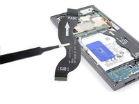
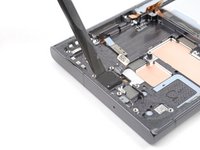
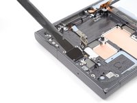
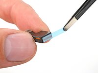
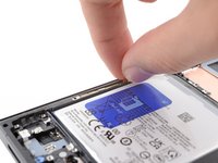
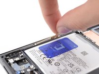
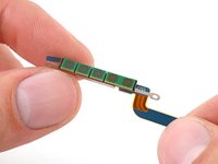
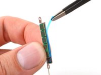
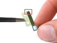
Insert the flat end of a spudger between the frame and the right 5G mmWave antenna connector.
-
Pry up with the spudger to separate the adhesive.
-
-
-
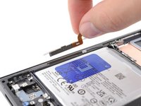
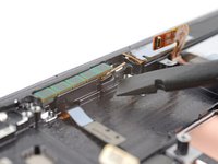
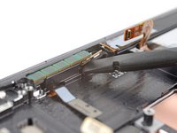
Remove the existing adhesive from the antenna with blunt nose tweezers or your fingers.
-
Remove the clear liner from your new adhesive.
-
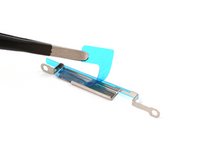
Apply the new adhesive to the bottom of the antenna, with its round end farthest from the connector.
-
Remove the green liner from the adhesive before reinstalling the antenna in the frame.
-
-
-
You're now left with the screen and battery assembly.
-


To reassemble your device, follow these instructions in reverse order.
Take your e-waste to an R2 or e-Stewards certified recycler.
Repair didn’t go as planned? Check out our Answers community for troubleshooting help.
To reassemble your device, follow these instructions in reverse order.
Take your e-waste to an R2 or e-Stewards certified recycler.
Repair didn’t go as planned? Check out our Answers community for troubleshooting help.
다른 6명이 해당 안내서를 완성하였습니다.


댓글 2개
Hola, compre une caisse completo para remplazar la pantalla, pero en el lugar de la pantalla tengo los revestimientos adhesivos azules de la cámara, como lo quito? por favor una ayuda