
Nintendo Switch Power and Volume Button Board Replacement

Follow this guide to replace the power and volume button board inside of a Nintendo Switch gaming console.
Note: This guide, and the part we sell, are compatible with the original Nintendo Switch model released in 2017, as well as the newer refreshed model released in 2019 (model numbers HAC-001 and HAC-001(-01), respectively).


-
-
Press and hold down the small round button on the back of the Joy Con controller.
-
While you hold down the button, slide the controller upward.
-
-
-
Continue sliding the Joy Con upward until it's completely removed from the console.
-
-
이 단계에 사용된 도구:Magnetic Project Mat$19.95
-
Use a Y00 screwdriver to remove the four 6.3 mm-long screws securing the rear panel.
I think my screws are stripped, any way to get them out?
I hear that using a rubber band can help? Not 100% sure on that though.
Pifase -
My top 2 screws are stripped, one into triangle, the other circle, rather than triangle spokes.
This happened when I replaced the micro-sd card slot, which turned out to have replaced the broken one with another one that turns out to be broken. I need to fix the fact that when I reapplied the back cover, the vent was misaligned.
I had huge problems removing the bottom two screws. I continued with the next steps and lifted the plastic shell as much as possible while using the screwdriver and it became an ease.
y0 works best. Press HARD at beginning then ease off to finish.
J LWsMommy - 답글
I haven't tried neither solutions that I am gonna propose here but
1. Poor some Isopropyl Alcohol, one small drop will do, get a piece of cotton (not any clothing) and dip it in the Isopropyl Alcohol, apply and then try to get a grip with tweezers and turn it out
OR (I do not reccomend it since it can cause huge damage if done wrong)
2. Grab a small drill and drill through the screw. Keep in mind; the screw is very small.
If you do one of these and it goes wrong, I am not responsible for that.
-
-
-
Use a JIS 000 driver or an official iFixit PH 000 driver to remove the following screws securing the rear panel:
-
One 2.5 mm-long screw on the top edge of the device
-
Two 2.5 mm-long screws on the bottom edge of the device
Hey guys, I tried removing the upper screw and it won't go out(neither will it go in) any tips how to fix this?
Thanks
The screw boss might be stripped out. Has the device been taken apart before? If you can unscrew it a little bit to get the screw to peek out, maybe try and grab it with some pliers as a last-ditch effort.
I have the same problem. The JIS 000 tool works great on the joy con rails per step 5 but refuses to turn the bottom two 2.5 mm screws as in step 4. These bottom screws are noticeably smaller than the screws as in step 5. The JIS 000 does not get down into these screws. Hopefully they haven’t been stripped by the wrong tool. So is there a JIS tool that is smaller than 000? I’m stuck at this point…
We used the JIS 3.0mm screwdriver for both top and bottom screws and it worked
Fun fact: these screw into little plastic tabs that stick out of the rear panel. Apparently those tabs are fragile and easy to just break off…
If the screw is turning but not coming out, the plastic tab that it screws into is probably damaged or broken. You’ll need to try to pry the screw out with tweezers as you unscrew it. It is not the end of the world if you can’t screw these back in during reassembly.
this screws are way too fragile and way too small so be careful when taking them off dont use much force and unscrew also one of them fell somewhere and spent 30 mins searching for it
PH000 will work if you don’t have JIS000. The large IFIXIT kit has both and I lost JIS000. Just be very careful as you can strip the heads when removing or inserting easier.
One thing that worked pretty well for me with the screws not coming out is slightly prying on the back cover to put them under some tension
I just came here to also confirm and say thanks to Florian for the tip. This saved me a lot of time and frustration.
Quick note, these screws are not magnetic. A magnetic screwdriver will hold onto any of the others safely, but you need to be careful not to drop these ones in particular.
Jason Lane - 답글
These would just keep rotating and not come out. What worked was, as Florian Kraupa suggested, i slid a plastic pick just between the 2 shells near the screws to prise it open slightly, then unscrewed and out they came. They're the smallest screws I've ever almost not seen before, so be careful with them.
Der Tausch von Akku (separate Anleitung) und Lüfter ging einfach vonstatten. Die Anleitung ist echt gut und leicht verständlich. Man sollte aber gewohnt sein, mit extrem kleinen Anschlüssen, Schrauben und Platinen zu arbeiten, da alles da drin recht klein ausgelegt ist und keine Toleranz für grobschlächtiges Arbeiten erlaubt! Meine Switch ist nun wieder wie neu :) - Danke iFixit!
The swapping of battery (separate instruction) and fan was fairly manageable. The instructions are easy to understand. One should be used to handle with extremely finnicky connectors, screws and circuits as the components are really small and do not allow any tolerance for rough handling at all! My Switch is good as new again :) - Thank you iFixit!
My original switch bought on launch day does not have any of these screws. I'm guessing they fell out since the plastic tabs they attach to are broken. FYI, in case anyone else does not have these screws...
-
-
-
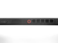
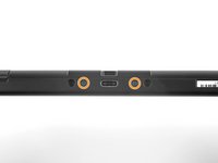
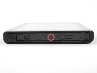
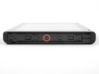
Use a JIS 000 screwdriver or an official iFixit PH 000 driver to remove the two 3.8 mm center screws on the sides of the device (one on each side).
I tried my JIS 000 on Step 5 and was unable to get the screw to budge. It’s partner from the other side came right out with no trouble. Don’t really want to narf up the screw, so I bailed out. Anyone else have this issue?
Could just be torqued down a bit more! I’d recommend making sure the driver bit seats nicely into the screw, apply some downward pressure, and slowly twist to try and back it out. Good luck!
Yeah I’m having this exact issue. Screw stripped and now I’m stuck. Wish I hadn’t even started.
What worked for me here was a Phillips 000, not a JIS 000
My kit only has two screwdriver heads! The package was open when I received it!
I had this issue as well. Screw was irreparably stripped. If you can get every other screw out, just keep applying pressure with a flat head screw driver right above the stripped screw and try to break the plastic piece holding onto the screw. It's a very minor invisible bit of damage that will allow you to continue the repair.
after getting all the other screws off I just hinged the back part away and it snapped off neatly where the rusted screw is. not the best solution but it worked.
Steve T -
One of my screws was SUPER attached too, but after following a bit noticed the one other in the left that got out nicely, had the plastic tab broken already! So I went ahead and broke the other tab too. So the two side screws are now holding nothing. But I think it will work thanks to the other 4 or 5 screws. Too bad!
-
-
-
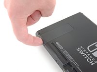
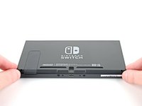
Use your finger to flip up the kickstand on the back of the device.
-
-
-
Open the game card cartridge flap.
-
Lift the rear panel up from the bottom of the device and remove it.
How to remove micro SD port?
Pull straight up, press back into place when closing back up.
This step is missing in this guide. Here are the steps from another guide:
Step 9) Nintendo Switch Right Joy Con Sensor Rail Replacement
Step 10) Nintendo Switch Right Joy Con Sensor Rail Replacement
When I lifted up the back cover, it kind of stuck near the headphone port (even with cartridge slot open). But it wasn't a screw or anything and I kind of carefully pulled and wiggled and the cover came off ok
+1, there is definitely an extra clip there on my day 1 switch
I wasn't so careful here and found out during reassembly that I accidentally broke off the clip with the screw hole on the top of the back cover (the clip fell off the device when I turned it over), so I can't put the top screw back in, but oh well at least the back cover is still affixed to the device otherwise
If you're having trouble getting the back cover to fit during reassembly, check to make sure you don't have an SD card inserted in the slot. It will get in the way.
If you're like me, you might have inserted the SD card to verify your SD reader was working again after doing step 9 reassembly. If so, remove it before proceeding.
-
-
-
-
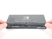
Use a JIS 000 screwdriver or an official iFixit PH 000 driver to remove the six 3 mm screws securing the shield plate to the device.
Some models have a small board in the lower left beneath the kickstand which accepts SD cards. This will have to be carefully removed with its connections popped out, then replaced after.
Yeah, that “small board” is the microSD Card reader chip, which was covered literally one step ago. All models have a microSD Card reader, that’s how game data is stored…
nin10doh -
My switch had loctite (or similar) on the bottom right screw (farthest right), ended up striping it and having to use a Dremel to cut a slot in the screw to get it out. I've heard that heat (solder gun) can be used to loosen loctite, hindsight. Only screw I found with loctite.
-
-
이 단계에 사용된 도구:Tweezers$4.99
-
Use your fingers or a pair of tweezers to peel back the piece of foam on the top edge of the device near the fan exhaust port.
My Switch (bought about two weeks after launch) seems to be missing this foam piece… Was it added later, similar to the foam piece in the left joy-con (to improve connectivity)?
It’s possible it was added to newer units! Nintendo slightly updated the internals of the Switch not too long ago.
My launch Switch also does not have this piece of foam, so it was most likely added later.
Also did not see this in my launch switch.
Me three, no foam.
-
-
-
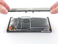
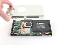
Insert a spudger underneath the shield plate along the edge of the device.
-
Pry up to lift the shield plate and remove it from the device.
-
You can reuse the pink thermal compound if you're careful. Keep the compound clean and make sure it makes solid contact between the heat sink and the shield during reassembly.
-
If you need to replace it, refer to our thermal paste guide to remove the old thermal compound and replace it with an appropriate compound, such as K5 Pro, during reassembly.
How do you know if the thermal paste needs to be replaced?
Youji Hong - 답글
Once you remove a heatsink you must always replace thermal paste even if you had just applied it ( or add a little more) . The reason is that once heat sink is fitted, paste splits around because of pressure and only needed amount will remain. If you remove the heatsink then some paste will move so when installed again there will be spots without paste. Hope this is clear enough. In any case cost of paste is very small compared to work time and value of your equipment…..
MacTek -
When your switch starts to lag and drop FPS, if you play breath of the wild and it starts to slow down in heavy areas like the forest where you get the master sword, can i use artic mx 4 insted of the pink compound?
Diego Soto - 답글
I’d like to know as well if a cpu thermal compound like arctic mx-4 can be used to replace the pink compound
No you shouldn't . It will spill around because it is not viscous enough and then there will be no heat transfer. As suggested by author K5 PRO is the most appropriate compound for such cases.
MacTek -
Arctic is generally only supposed to be used on bigger heat sinks like a personal computer. Its not nearly as thick or gummy compared to K5 PRO, and you should always use something that’s thicker for smaller project like a Switch/phone/tablet.
Why was this not included in the tools/equipment list? Getting to this step and now I will have to reverse and wait for yet another order to arrive. ? Very frustrated
Hi Amanda,
Thanks for bringing this up. Sorry! We inadvertently left that part out during the guide refresh. I’ll add the necessary info into the step.
I agree with Amanda, hopefully I don't lose any parts before I can get the paste. This seems like it should almost be included in this kit from what I've read about this repair. Mine certainly needs to be replaced. I feel like at the very least, this should be at the top of the guide and part order page in bold, red, all cap lettering.
Side note this is the only "issue" I've had of the 4 purchases I've made with ifixit. I recommend you guys every chance I get. I really enjoy doing these repairs with my son.
does ifixit not have an appropriate thermal paste for this step?
there is only arctic silver 5 in the kit and i would guess that that should not be used in this case.
if true, the kit is incompleteLucas Tigy - 답글
Since I couldn't find decently priced K5 I used a 0.5mm thick thermal pad and that seems to have done the trick quite well.
The Amazon link goes to a kit with 6 tubes of K5 Pro. Surely I don’t need 6 tubes… is this kit sufficient? https://a.co/d/5aU8kB7
When replacing the thermal paste, is it possible just to clean the old thermal off the back plate and top of the copper heatsink and just re-apply those areas only, without removing that copper heatsink?
Linn Mckay - 답글
-
-
-
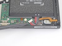
Use the point of a spudger to pry the battery connector straight up and out of its socket on the motherboard.
be careful not to pry it off the board entirely
This was an old switch and the entire thing with the black plastic came off.. Most of the pins aren't there anymore, too.. is there a solution to that? Does soldering work?
it's probably possible, but unless you have experience with microsoldering, you'd probably be better off taking it to a local repair shop
You can use a spudger to hold down the black plastic side of this connector that is supposed to stay attached to the motherboard while using the pointy spudger as shown in order to reduce any chance of pulling the socket off the motherboard.
-
-
-
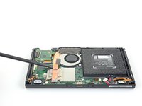
Use a JIS 000 screwdriver or an official iFixit PH 000 driver to remove the three 3 mm screws securing the heat sink to the motherboard.
-
-
-
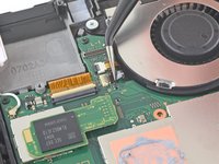
Carefully peel the two foam pieces stuck over both the heatsink and the fan away from the fan.
-
Insert the point of a spudger underneath the part of the foam that isn't stuck against anything,
-
Press the top of the foam with your finger to hold it in place.
-
Roll the spudger tip underneath the foam all the way to the other end of the foam to release it.
Maybe it’s because I’m working on a day one switch and the adhesive is just old and stubborn, but this didn’t work well for me. Am I just completely out of luck, or can I order a replacement for the foam?
Trae Block - 답글
I had the same problem and I found a foam manufacturer: https://www.foam-material.com/sample-cus...
I'm pretty sure the type is "Granular Activated Carbon Foam" and the thickness is 0.5 mm but I have no idea what the porosity is.
Yeah ripped the foam. Neither the screwdriver nor spudger technique worked. Day one switch, so 6 years old at this point.
Ndragonawa - 답글
Does the foam need replacing if torn? What does it actually do.
I wanted to know as well, what does it do? Can I replace it with thermal pads?
Can I replace the foam with a 0.5mm thermal pad? Will it be a better solution?
The adhesive remover really helped here being a day one switch
how do you re-glue the foam when putting this back together?
-
-
-
Use a spudger or your fingers to lift the heatsink up and off the motherboard to remove it.
-
Apply thermal paste to all surfaces that had thermal paste applied previously. This includes between the heatpipe and aluminum shield, which the Switch uses as additional heatsinking.
What's on the heatsink?
where do i get more of that black fabric like tape that is on the heat sink?
They may sell it in the ifixit store.
(1) Exactly how much thermal paste should be applied to the CPU?
(2) Which application method should be used? The linked instructions list four methods (vertical line, horizontal line, middle dot, or surface spread) but it’s not clear to me which one is appropriate for the Switch. Thanks!
UPDATE: So, for anyone who also wanted to know the answers to these questions:
1. I ended up eyeballing the amount. Imagine an amount the size of a pea, then split that amount in half. That’s how much I used, and it worked fine.
2. The paste (I used K5-Pro as recommended) is quite thick and sticky and difficult to get to behave the way you want, so I ended up just doing the “middle dot” method and spreading it a bit with a popsicle stick before smushing it the rest of the way down with the heat sink. Seems to have done the trick.
Good luck!
Travis -
you can also spread it with the spudger or any non-metalic tool if you are not sure how much you put
just clean it afterwards
K5 (or thermal pads) is ONLY needed between the copper pipe and metal shield plate. It is a pad replacement compound and is not meant for high heat applications like CPUs as it boils and creates air gaps. Air=bad for heat transfer.
Regular thermal compound/paste should be used on the CPU. You’ll have a sticky mess to clean but if you want proper cooling it needs to be done. The instructions clearly state that regular compound is used on the CPU.
Cerus98 -
i used artic silver 5 and worked just fine
The steps doesnt specify but do you have to remove the heat shield from the cpu as well?
-
-
-
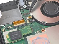
Use an opening tool, spudger, or your fingernail to flip up the small, hinged locking flap on the fan cable ZIF connector.
The little gray tab flew off while I removed the cable. I found it, but I can’t get it back on. Is it possible to install the new fan without it?
No. You will need for professional help to replace the whole ribbon cable connector (ZIF connector).
CCL13 -
I have the same issue, and to make matters worse, my fan isn't working now. I'm not sure if it's a problem with the interface or the fan itself.
argxuy -
A step here is skipped. There is a small board which contains the cart reader and headphone out jack. The connector for the headphone jack will need to be popped off and the board unscrewed. It can then gently be pushed out of the way while leaving it otherwise connected. Reconnecting the headphone jack’s cable is tricky as a heads up. Be patient there.
That step is immediately above this one. Check out step 21 to 23.
CCL13 -
-
-
이 단계에 사용된 도구:Tweezers$4.99
-
Use a pair of tweezers to pull the fan cable straight out of its connector on the motherboard.
Will need to remove parts and board in top left in order to get to 3rd fan screw.
During reassembly, I found it easier to insert the ribbon from the new fan while the fan was loose and held in my hand. Once the ribbon was inserted and locked down, then I seated and screwed in the fan.
-
-
-
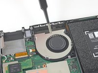
Use a JIS 000 screwdriver or an official iFixit PH 000 driver to remove the three 4.8 mm screws securing the fan.
Petite erreur, il n'y a que 3 vis qui fixent le ventilateur. Merci pour ce très bon tutoriel!
Bonjour @mikaelchola, merci de votre remarque. Je viens de corriger l'erreur. iFixit étant un wiki, sachez que vous pouvez aussi effectuer toutes sortes de modifications. Encore merci et bonne continuation à vous !
-
-
-
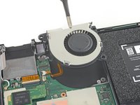
Use a pair of tweezers or your fingers to lift the fan straight up and remove it from the device.
The original fan does not have removable rubber bushings. It has hard plastic ones attached to the fan itself. The original fan is a Foxconn PVB040A05H brushless fan.
Because I cannot remove the brushings but the guide assumes I can, the new fan cannot be screwed in securely, so my repair seems to be failing.
I ended up using 2 tiny regular metal washers per screw and closing it back up. The washers prevent the fan from moving up and down but not side to side. The heat sink probably holds the fan in place well enough that I didn't even need the washers. Either way the replacement fan isn't quite as secure in there as the original. But the repair works -- for anyone else stuck at this step.
Same here. WTF is wrong with this "repair" kit?! I CANNOT repair my Nintendo Switch FFS!
Steffen -
My switch did have rubber bushings that I transferred to the new fan. The old fan was from Delta Electronics.
The fan in my switch did not have bushings either. This replacement kit should be revised to include them.
Come on... The Foxcon model: PVB040A05H-P05 has no rubber bushings. THIS is f*cked up. Now I am sitting with my opened Switch and cannot replace the fan.
My switch had the rubber bushings on the fan already. I took the rubber bushings off the old fan and put them onto the new fan.
I had the same issue with my original being the foxcon fan. I don't recommend it, but I cut the hard rubber bushings out of the old fan using a Dremel or nail tool and then shaped it to the new fan. It was tedious and not worth the effort in my opinion, but it did work
This is profoundly disappointing! I have been relying on iFixit for decades and this is the first time I opened up an entire device in vain because of iFixit supplying a garbage replacement part. My oldest switch had the grommets, but newer models have built in plastic. iFixit could have spent 20 cents on the grommets and I would not have risked damaging a $400 machine on a worthless replacement.
i just used some rubber heat shrink tubing and cut it to size and poked a hole in it.
I didn't have any bushings in my old switch, and couldn't come up with a reasonable "shim". Probably not the best idea but I opted to add a couple small dabs of super glue to the bottom side of the fan to help secure it in location. Hopefully I don't need to remove it in the future.
-
-
-
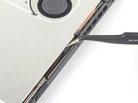
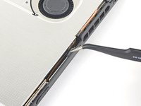
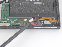
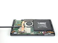
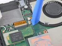
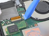
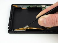
Use a spudger to flip up the small black locking flap on the power/volume ribbon cable ZIF connector.
-
-
-
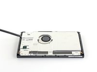
Use the flat end of a spudger to pry up the taped down power/volume ribbon cable.
I was able to replace the LCD and touch glass on my son's Switch. Everything went well the LCD worked again the screen too ... everything really ... except the ON / OFF buttons and volume ... I opened the switch again and tried to put the Ribbon Flex Cable back on the ZIF connector. As I was getting unnerved, I ended up detaching the ZIF connector from the motherboard, which came out broken. Now I look for this ZIF connector on the internet and I can't find it. Can anyone help me? Thank you
-
-
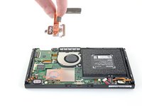
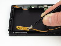
이 단계에 사용된 도구:Tweezers$4.99
-
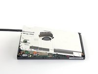
Remove the power/volume board with a pair of blunt nose tweezers.
-


To reassemble your device, follow these instructions in reverse order.
To reassemble your device, follow these instructions in reverse order.
다른 15명이 해당 안내서를 완성하였습니다.

댓글 8개
Great guide. Just repaired my daughters Switch by replacing power button.
I replaced the cable and still have the same issue, volume up button don't work and volume down is volume up, and it's always kn
Hi, did you manage to fix it? I have the exact issue
I changed the cable and it works.
Thanks
Great guide. There were a couple of steps I found missing, but the rest of the guide had very similar steps, so just applying the same logic to the mini-boards I had to pull worked perfectly. This guide saved me from having to buy a new switch or pay almost the price of a new one to have it repaired!
Guide was almost perfect - two important steps missing: one step for each of the card readers. Which are kind of important, as if the game card reader isn’t reconnected properly, the console won’t boot back up. Fortunately, I figured that problem out before bricking my switch.
Great guide. However, this guide did miss how to disassemble the game card reader which should be done before step 18 since the cartridge slot is blocking one of the screws of the fan. All that is required is to unscrew three (i think they're 3mm) screws and take out a little plastic black piece that was screwed in. Then, you have to pull out the ribbon closest to the fan. (This may take a bit of a hard tug to get out but it should be fine.) After that, the cartridge slot should only be connected via the other long horizontal ribbon to the left and you don't have to do anything because at this point you should be able to move around the cartridge slot and be able to unscrew the fan now. Sorry if this is a bit unclear because this is my first time doing anything like this but I thought I could try to help other people having problems.
Kann ich diese Anleitung auch für die OLED anwenden? Habe im INet sonst leider nichts brauchbares gefunden.
Ina Barz - 답글
backup all your sd card data i had to format mine after this tutorial and lost all my game data
JustForThisComment?ComeOn - 답글
do not watch the video! i broke the metal shielding on my switch because they didn't mention a screw!!!
Macro Man - 답글